Continue to Site

Eng-Tips is the largest engineering community on the Internet

Intelligent Work Forums for Engineering Professionals

  • Congratulations The Obturator on being selected by the Eng-Tips community for having the most helpful posts in the forums last week. Way to Go!

NPT thread strength - Stress Distribution / Tensile Area 1

Bruno730

Mechanical
May 17, 2025
5
Hi all

Having a debate with a few friends (some engineers and some non-engineers, but mechanically inclined). For an NPT threaded pipe connection under a tensile load, is the load applied to:

> ONLY the last engaged external thread;
> Distributed evenly across all engaged threads, or;
> Highest at the last engaged thread and then decrease with increasing distance from the end of the connection?

We look forward to the conversation!
 
Replies continue below

Recommended for you

The trouble with NPT is the variance in engagement. The cross section area varies based on engagement depth.
 
mfgenggear, None of those are pipe threads.


See

Tapered threads are more likely to better distribute the thread load, hence they are very popular in the down-hole drilling industry where a string of pipe sections that can be miles long are assembled with sections of pipe with tapered thread. They also engage much faster, which is also a source of popularity.

That said, the typical above ground tapered thread installation doesn't have nearly as much elastic conformance to provide load distribution, so they will be somewhere in the middle with the non-uniform distribution of straight threads on the other side. The taper is also shallow so they don't have a quick-engage mode.

Elasticity rules out the first conclusion; if it was only the first turn of thread then no other turn of thread could possibly be in contact. That would require both parts to be infinitely rigid or that there be only the first turn of thread.

Distributed evenly is also unlikely as there are small variations in thread form. They won't necessarily be as unevenly distributed as straight threads, but it won't be even.

Elasticity rules out the last one for the same reason it rules out the second one. It could happen but it doesn't have to happen.
 
Yes I know , there are pipe thread calculation out there, maybe even machinist hand book.
But according to the first post I did, the author
Commented on the first couple of threads having the most stress. Is that not applicable?
 
is the load applied to: Highest at the last engaged thread and then decrease with increasing distance from the end of the connection?
Yes, that's true of every bolted joint regardless of thread type. Your highest load, highest stress, and therefore largest thread concern is always in that first thread.

The difference between straight and tapered threads of identical major diameters in that circumstances isnt the loading, its the stress in each thread. As you move along the straight thread, stress decreases bc F/A; F decreases and A remains the same. As you move along the tapered thread both decrease.

Tapered threads are rarely used to support structural loads bc they're a compromise. You get a thinner sectional area vs straight threads bc you dont need a shoulder but OTOH the taper induces radial stress causing thread/material wear, and ultimately straight threaded joints are stronger and less likely to fail.

This is overall consistent with my argument and logic. The thin and varying wall thickness is a limitation with tapered threads.

I suppose that Machinery's Handbook and other references do not have data for tensile stress area of NPT threads because it is changing along the length of engagement, as opposed to straight threads.

Nevertheless, from an analysis standpoint, I figure you would probably want to evaluate the tensile area at one specific location along the joint, such as the location of minimum wall thickness. Yes?
 
I am very interested in what the OP discussions have been, particularly with regards to specific applications.
 
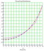
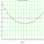
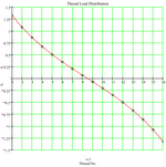
I found this subject interesting and investigated it some time back (15+ years). Although I reviewed standard thread types (Metric and UNJ), and I agree that the taper will influence the load per thread through the axial joint (differing cross sections along thread engagement), I would think the difference in the thread load distribution seen under differing load path applications would be similar. The following three figures illustrate typical thread load distributions under differing load applications.


Typical load distribution under preload conditions (thread 1 at the free end of the bolt thread).

1747556899574.png


Typical load distribution under an applied tensile or compression load, where the load path is from the bolt thread undercut, through the thread engagement length, and reacted at the end of the nut (fixed face).
1747556975115.png


Typical thread load distribution, where the load (compression or tension) is through the two side faces of the nut (sum of thread loading to be zero).
1747557480983.png

Edit - For the second condition, screwing a bolt into the end of a tube and pulling on the bolt and tube would be the same load path.
 
Last edited:
I am very interested in what the OP discussions have been, particularly with regards to specific applications.

The conversation started about why you don't see NPT threads in structural applications. Normally, NPT use is limited to fluid conveying pipes or similar systems.
 
I found this subject interesting and investigated it some time back (15+ years). Although I reviewed standard thread types (Metric and UNJ), and I agree that the taper will influence the load per thread through the axial joint (differing cross sections along thread engagement), I would think the difference in the thread load distribution seen under differing load path applications would be similar. The following three figures illustrate typical thread load distributions under differing load applications.


Typical load distribution under preload conditions (thread 1 at the free end of the bolt thread).

View attachment 9684


Typical load distribution under an applied tensile or compression load, where the load path is from the bolt thread undercut, through the thread engagement length, and reacted at the end of the nut (fixed face).
View attachment 9685


Typical thread load distribution, where the load (compression or tension) is through the two side faces of the nut (sum of thread loading to be zero).
View attachment 9686

Can you explain this more? I don't follow the testing setup or what you mean by "the load path is from the bolt thread undercut, through the thread engagement length, and reacted at the end of the nut"
 
The conversation started about why you don't see NPT threads in structural applications. Normally, NPT use is limited to fluid conveying pipes or similar systems.
Because they have a fixed engagement position would seem to me to be the main reason. I can cut a piece of threaded rod that's 10 feet long into just under 3 inch pieces and every piece can be used to clamp metal together, which tapered threads cannot.

If you don't think dropping 10,000 feet of steel drill string down a hole to spin a cutting head into rock is structural I am not sure what to make of that, but those connections are only at the ends of the sections.

How do you imagine a tapered thread would be used to replace straight thread bolts or all-thread rod?
 
The other thing is that oilfield threads are a lot different from NPT.
They are much tighter tolerance and they usually tighten against a shoulder.
And with NTP being a highly truncated thread form the amount of engagement has more variation than with other thread forms.
I have used NTP where the female component was very stiff and strong.
I still couldn't accurately predict the strength of the connection.
We did a lot of modeling and testing.
 
True - I was referring to the generalized use of tapered threads and their limited axial location capacity.

NPT on its own is optimized for pipes, not structures, and is not suitable for applications where broad axial adjustment is expected or wanted.
 
Last edited:
Researching this a bit.
NPT specifically designed for tight seals.
There is very little out there on stress analysis.
Except FEA.
 
Researching this a bit.
NPT specifically designed for tight seals.
There is very little out there on stress analysis.
Except FEA.

Yes, exactly what I was finding too. The lack of information is surprising unless a large failure occurred a long time ago and it became anecdotal knowledge to NOT use NPT for axial load applications.

Nevertheless, for modeling and discussion purposes, would you only evaluate the wall thickness at the last engaged NPT thread (i.e., not the free end)? It seems like that is the case for straight threads based on the tensile stress formula.
 
Because it is so unpredictable. Hydraulic systems manufacturers moved away from NPT decades ago due to its poor fatigue performance.
 
Because it is so unpredictable. Hydraulic systems manufacturers moved away from NPT decades ago due to its poor fatigue performance.
When the design goal is to make a cheap connection that will fracture unpredictably under external load, NPT is perfect.
 
Still no indication of what kind of "structural" joint was being discussed in the first place.
 

Part and Inventory Search

Sponsor