Continue to Site

Eng-Tips is the largest engineering community on the Internet

Intelligent Work Forums for Engineering Professionals

  • Congratulations KootK on being selected by the Eng-Tips community for having the most helpful posts in the forums last week. Way to Go!

Can IC Engine Compression Testing with/without Blanks on Inlet and Exhaust Manifolds Quantify Valve Leakage? 1

yamoffathoo

Mechanical
Sep 19, 2008
95
I am considering refurbishing a 200,000 mile 2.4L, 4 cylinder engine sitting in my shop.
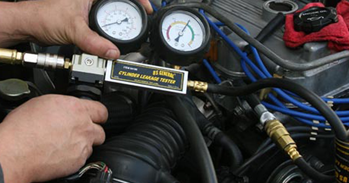
Compression testing at 250 rpm yields 90 psig, which increases to 120 psig with 3 squirts of oil in the cylinders, which is below the 140 psig minimum.
To determine whether inlet and exhaust valves are contributing and need lapping, would blanking both manifolds, then each one at a time and recording changes in peak compression numbers yield useful results?
How much compression increase in either valve train would indicate that lapping is required?
Lifter gaps are within specifications, so I am looking for a reason not to disturb them at this time.
Any suggestions would be welcome, thanks.
 
Replies continue below

Recommended for you

OP
Look into the leak down procedure. Verify at each cylinder in the top dead center from what recall, how ever I have not done it on while .
So research it verify it. Proper equipment is required. Also Pump air in each cylinder at top dead center and then verify if air is passing or leaking in the exhaust manifold, intake, or the oil dip stick. At 200k miles. Possible needs a rering, and valve job.a proper compression verification should be engine not running. And cranked several cycles. If compression jumps after oil squirter , it is compression rings ate worn. High oil combustion, carbon in cylinder, and on spark plugs , worn oil rings. Burn or warped valves will be detected by the leak down test.
 
mfgenggear,

Compressed air injection and leak down measurements would be heavily influenced by piston ring leakage.
No detectible leaks past the valves would be perfect but how do I decide what is an acceptable leak rate?
 
The important variable is valve to seat contact area. To check it, apply a bit of dykem to the seats and rotate a valve 10* back&forth is both direction 2-3x. You want a consistent, wide contact area all the way around.
 
63691_I.jpg


But seriously, you'll spend more time doing tests and trying to figure out what's good and what's bad than you will to just do a proper job.

Just lap them.
 
mfgenggear,

Compressed air injection and leak down measurements would be heavily influenced by piston ring leakage.
No detectible leaks past the valves would be perfect but how do I decide what is an acceptable leak rate?
Some times it is difficult. According to this article 10% loss is acceptable. But in your case there is to low of pressure. It's time to disassemble. Then repair. I for got to mention all possible leaks. Intake valve air coming out of intake. Exhaust valve air leaking thru exhaust.
Bubbles from radiator. Head gasket.
Rings air leaking into oil chamber.
Inspects valves for burn carbon built up, warped or burn. Inspect head for flatness. Inspect head gasket for breaks or damage. Mark and tag each rod and bearing assembly with piston for correct order. Disassemble and inspect. Remove and replace rings. Remove and replace valves rework or replace, must be lapped in place. Rework at a head shop to grind the correct valve angle. The lap. Inspect rod and crank bearing became full to mark or stamp correct order. Have head resurfaced if necessary. Purchase over size thickness head gasket.
 
It's all was good practice to rering and valve job concurrently.
PS : I for got to add inspect the piston cylinder.
A heavy ridge at TDC means wear. Rent a bore gage if ridge is minimal. Buy a stone style
Hone and lightly to get a spiral .
Lube all component well . Buy a good service manual on eBay. It will really help.
 
Last edited:
There is a proper method (and a proper tool) to do a cylinder leak-down test. It is more-or-less two pressure gauges with a calibrated orifice between them, with compressed air fed in through a regulator to the gauge on one side and compressed air from the other gauge leading via a hose to an adapter that screws into the sparkplug hole on the other side. While feeding compressed air in via this device, it's pretty easy to listen and feel at (1) the (removed) oil fill cap or dipstick hole, (2) the throttle body, with intake duct disconnected upstream of the throttle itself, and (3) the exhaust pipe.

You can rig up compressed air to a compression-tester fitting (sparkplug adapter) without the gauges if you just want to qualitatively see what's knackered ... though it's probably everything. Obviously this testing has to be done with that particular cylinder at TDC between compression and power stroke (all valves off their cam lobes).

If the engine has shim-and-bucket fixed valve mechanisms - no automatic hydraulic lash adjusters - do check for proper valve clearances, as tight clearances will show up as leakdown.
 
For rookies that don't know, a compression test will diagnose the health of your engine.
The compression tester is a necessary tool.

A leak down test will diagnose where the problem is. Leak down gage are helpful
To indicate the rate of leak and where.
When the two test above indicatec an issue
Then an actual tear down and inspection will be required. For issues for repair or replacement.
 
You can test for leakage with the camshafts removed by filling the ports with solvent. If you see anything dripping from the closed valves, they're leaking.

Better yet, measure valve protrusion. A worn valve will show excessive protrusion. Worn valves don't always leak.
 
Thanks for all the suggestions, however since the engine is on the bench with inlet and exhaust manifolds removed I was hoping for comments about my fairly simple proposal to alternately blank the inlet and exhaust ports while cranking at 250 rpm:

a) no lapping required if no peak pressure increase when both blanked.
b) lap exhaust valves if peak pressure increase with exhaust port blanked.
c) lap inlet valves if peak pressure increase with inlet port blanked.
 
Just do a cylinder leak-down test ... whether instrumented or not. I don't see how your proposed test would produce meaningful results.
 
Lapping is a finishing method used after grinding valves. The valve face is wider than the contact area of the seat under normal conditions. Lapping the valve against the seat does not correct issues with valve face wear.
 
For one thing, if you blank off the intake manifold, the spinning engine will pull a vacuum in the intake manifold, thus inherently lowering compression (because there's less air-mass to compress). "By how much", who knows, because that vacuum will be partially broken by the simultaneous opening of exhaust valves prior to intake valve closure during the valve-overlap period. It will not produce a meaningful result. Likewise, blanking off the exhaust manifold will turn the engine into a dead-headed air compressor, although the total pressure will be partially relieved by the above-mentioned valve overlap period.
 
OP
Apply blue dykem or equivlant on the valve angle faces .
Apply on each valve and head angles/seats.
Spin the valves , then take picture. This depicts if the valves are seating correctly.
Lap them all and repeat. If after inspecting.
All valves must seat. If not the a grind is required. Do you have any mechanic experience?
 
No, your proposed tests are useless.

Apply compressed air and listen for a leak at each port.

Or, if it's on a stand then you could rotate it until the intake or exhaust ports are up and then put some mineral spirits into each port and see if any leaks into the combustion chamber. Rotate the engine again to dump it back out.
 
Okay, Okay, I'll eat some crow on that idea...but here's another one (please see attachment).

This quick measurement can detect excessive connecting rod big end bearing wear without having to disassemble and do the plastigauge routine as follows:

1) mount a 12" dia degree plate on the drive pulley threaded extraction stud holes
2) install a pointer nearby secured to the casing
3) install a brass rod in a steel guiding pipe that threads into the spark plug hole
4) mount a dial gauge on the steel pipe to detect vertical movement of the brass rod sitting on top of a piston.
5) rotate the crankshaft clockwise up to TDC then continue rotating and note the angle when the dial gauge begins to detect downward movement
6) rotate the crankshaft counter clockwise back up the TDC then continue rotating and note the angle when the dial gauge begins to detect downward movement
7) add up the angles and consult the table on the attachment, which will tell you what the big end bearing gap is.

This method relies on the piston rings being able to grab the cylinder and support the piston weight as it loses support from the rod.

For a 12"diameter degree plate, a gap of 0.01mm converts to 2.34/360*pi*12"=0.245", which is very easy to detect as movement on the degree plate perimeter.

Any comments are appreciated, thanks.
 

Attachments

  • Con Rod Big End Bearing Damage Detection flat.pdf
    174.6 KB · Views: 2
So if you are refurbishing this 200k engine, why not do it right? Get a valve job. Measure the cylinders . If they are out-of-spec, have it bored, Put in all new bearings etc.
 
Okay, Okay, I'll eat some crow on that idea...but here's another one (please see attachment).

This quick measurement can detect excessive connecting rod big end bearing wear without having to disassemble and do the plastigauge routine as follows:

1) mount a 12" dia degree plate on the drive pulley threaded extraction stud holes
2) install a pointer nearby secured to the casing
3) install a brass rod in a steel guiding pipe that threads into the spark plug hole
4) mount a dial gauge on the steel pipe to detect vertical movement of the brass rod sitting on top of a piston.
5) rotate the crankshaft clockwise up to TDC then continue rotating and note the angle when the dial gauge begins to detect downward movement
6) rotate the crankshaft counter clockwise back up the TDC then continue rotating and note the angle when the dial gauge begins to detect downward movement
7) add up the angles and consult the table on the attachment, which will tell you what the big end bearing gap is.

This method relies on the piston rings being able to grab the cylinder and support the piston weight as it loses support from the rod.

For a 12"diameter degree plate, a gap of 0.01mm converts to 2.34/360*pi*12"=0.245", which is very easy to detect as movement on the degree plate perimeter.

Any comments are appreciated, thanks.
Too many uncontrolled variables/sources of error is my immediate thought.
 

Part and Inventory Search

Sponsor