Continue to Site

Eng-Tips is the largest engineering community on the Internet

Intelligent Work Forums for Engineering Professionals

  • Congratulations cowski on being selected by the Eng-Tips community for having the most helpful posts in the forums last week. Way to Go!

Tapped axial holes on tube

sleepdrifter

Mechanical
Mar 21, 2025
18
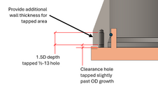
I have to design a fixture that is a roughly a 23" ID tube w/ a 1" WT that will have a tapped bolt pattern around the flat base portion of the tube. I've been trying to find how I can calculate what kind of stress would cause the part to fail. My biggest concern is that I'm aligning with 1/2" clearance hole BP so I'm aiming to use 1/2"-13 tapped holes and the slimmest margin I have from major diam of tapped hole to my part OD is roughly .175".

What sort of equations should I be looking at to confirm that I'm not going to shear the threads off since I don't have much material between the tapped hole and OD of the part? Less worried about shearing threads off and more so a major deformation of the thread area due to a thin wall thickness. I've abided by the rule of thumb 1.5D of wall thickness for steel but how can I mathematically determine if my design is prone for issues?
 
Last edited:
Replies continue below

Recommended for you

Thank you all for the responses. I'm pretty limited on my design options due to customer constraints. I can't make any changes to the orange part; I have to work within the constraints of that component.

My primary concern here is the OD area goutam pointed out tearing out. I am using a 1/2"-13 thread here because the customer component in orange has 1/2" clearance holes. I fear going with a smaller screw size to provide more wall margin on the tapped holes will introduce other issues with the screw having too loose of a clearance hole.

What type of equations and stresses should I be looking at if I want to focus primarily on the OD area tearing out? If I can justify that this area is strong enough for my testing case then I don't need to complicate things further. The orange plate I've shown is a vast simplification of the actual part I'll be testing upon

I've been thumbing through shigley's and haven't been able to find anything that exactly pertains to this type of situation.. is the edge to hole distance rule of thumb derived from actual testing or are there some calculations behind this I can use to determine if this design will fail or not? I wasn't looking for design advice just yet because this is the simplest way to achieve my requirement without overcomplicating the design and increasing the cost of producing the part. I'd like to prove this design is prone to fail before I get back to the drawing board with a complicated 2-3 piece design.
 
The lip on the OD of the orange part is only 0.15" tall. My current concession it to clear that lip vertically then expand out the OD of my part to allow for a much larger material margin between the OD and my tapped hole. I would have a clearance hole in the area with little material on the OD then tap a hole in the length where I can increase wall thickness. Does this appear to be a much more sound and safe design overall?
 

Attachments

  • 1746203449064.png
    1746203449064.png
    60 KB · Views: 6
Last edited:
Given that this is essentially a plug which is being held in, why don't you use the upstand flange which is already there and hold the plug in with a set of pins in shear into the whole of the wall thickness??

You could probably tap the up stand flange element to make the pins flush.

See below in green - possibly a bit hard to see... And ditch the blue bolt. You might need double the number but at least there is only shear to worry about?

View attachment 8969
I'm unable to modify the orange part at all. I'm handed a part from a customer and have to create a fixture to seal and pressurize it to validate the integrity of some bonded seals/components not shown in my simplified figures.
 
OP
The assembly is considered a screw assembly.
Scroll through this attached pdf. It may help.
 

Attachments

  • Ch_8_slides_m_250502_094930.pdf
    4.6 MB · Views: 2
The lip on the OD of the orange part is only 0.15" tall. My current concession it to clear that lip vertically then expand out the OD of my part to allow for a much larger material margin between the OD and my tapped hole. I would have a clearance hole in the area with little material on the OD then tap a hole in the length where I can increase wall thickness. Does this appear to be a much more sound and safe design overall?
Yes it does.

That's what I was suggesting in post #17, but if you can make it as a ingle forging or similar than that's better than added reinforcement.
 
The lip on the OD of the orange part is only 0.15" tall. My current concession it to clear that lip vertically then expand out the OD of my part to allow for a much larger material margin between the OD and my tapped hole. I would have a clearance hole in the area with little material on the OD then tap a hole in the length where I can increase wall thickness. Does this appear to be a much more sound and safe design overall?
At a glance I prefer this one. And you can start the threads a bit deeper in the thicker metal where they'll be well supported.
 
OP
The assembly is considered a screw assembly.
Scroll through this attached pdf. It may help.
Thanks for this.. it's a lot more digestible than the textbook.

Yes it does.

That's what I was suggesting in post #17, but if you can make it as a ingle forging or similar than that's better than added reinforcement.
Appreciate that.. I think this is my best option without overcomplicating things.

Thanks again everyone who spent some time responding to this.

My final question: is calculating thread tearout/material failure due to not enough wall thickness a reasonable thing to do without relying on FEA? Stress_Eng provided me with some direction that I'd like to look into more, but I'm having a hard time finding anything in any books or online of why edge distance is at least 1.5D. Is there any straightforward way of me calculating material failure given loading conditions on the threaded hole?
 
OP "The plate will have an oring to seal off the assembly..."

If the drawings are representative, I am curious how this thing gets put together such that the O ring winds up in the right place, between the two shallow grooves.

Regards

Mike
 
I think there is a groove on the inner portion and the model does not include the deformation of the o-ring. However, the groove is sufficiently shallow that there is no hope of it staying in place.
 
OP "The plate will have an oring to seal off the assembly..."

If the drawings are representative, I am curious how this thing gets put together such that the O ring winds up in the right place, between the two shallow grooves.

Regards

Mike
Radially sealed with an o-ring that sits inside a groove on the orange component. I didn't include the detail in my power point engineered representation of the orange component.
 
The tube wall exceeds the dimensions of a 1/2-13 nut as first mentioned by MintJulep. Would a low-strength, A-36 nut provide enough clamping force and thread strength?

nut.JPG
 

Attachments

  • Article - Screw Threads Design.pdf
    848.5 KB · Views: 1
This NASA paper presents a conservative calculation for pullout strength, and tabulates it for various materials.


The pullout strength formula presented is:

1746233260034.png

Note that the 3 is an arbitrary factor of safety.

1/2"-13 Grade 8 bolts torqued to 80 lb-ft are likely to strip threads tapped in A36. It will depend on how lubricated or not the screw and hole are. Since you've stated your intent to use anti-seize you'll certainly strip the threads.

As I noted before, there's a huge mismatch between bolt capacity and load - like about a factor of 60.
 
Ok, so no groove in the grey part. I think the groove in the orange part must be deeper. O rings want close fits and fine finishes. Recommend the Parker O ring handbook, freely available online.
 
@sleepdrifter

Sorry, I confused the direction of force. Refer below:

1746242799543.png

Now considering the statement by @MintJulep that the bolts have excess strength, I try to concentrate on the expansion force below. Note: it is difficult to predict (without FEA) the distribution of stress between pipe body and the bolts and I assume only 1bolt D height of the pipe is affected by the inclusion of the bolts.
1746242403537.png

So I think enough safety factor is available for the assumptions taken. But more thorough analysis possibly with FEA should be undertaken for a firm conclusion.
 
Did some cylinder calc's using assumptions (method not checked). I think earlier in the post you said you'd like to make your part out of Aluminum.

Used inputs.
E = 10007.6 ksi (used 69 GPa)
Poisson's ratio = 0.33
Vertical cylinder length = 12.008in (assumed, used 305mm)
Unpressurized length at base = 0.984in (assumed, used 25mm)
Radius = 12.402in (used 315mm)
Thickness = 1.0in (25.4mm)
Internal pressure = 20 psi (used 0.138 MPa)
Boundary conditions - Fixed radial displacement at both ends, zero rotational restraint at both ends.
(loading is circumferential distribution)

Results
Distributed shear at base = 16.52 lbf/in
Cylinder rotation = 9.386 x 10^-5

Cylinder rotation will put bolts into bending.

Edit - Results for fixed radial displacement at both ends, zero rotational restraint at top and full rotational restraint at base.
Distributed shear at base = 49.23 lbf/in
Distributed BM at base = 106.74 lbf.in/in
 
Last edited:

Part and Inventory Search

Sponsor