alphanumericname
Structural
Hello,
I am designing a pier-slab moment foundation to support an 85' pole that is loaded in two directions. The pier is 6'x6'x11', the slab is 20' x 20' x 3', and the slab will sit 10.5' below grade on excellent quality limestone. The excavated soil will be backfilled with gravel. It will have foundation design loads as follows:
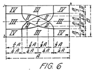
I do not have access to any software to assist in this design, instead I am using an article from a 1927 engineering publication that was given to me by a coworker. I could not find the article with a cursory google search, but I've scanned a picture of the loading regions (see below) and it falls into the "Case II" loading category, which results in one corner being in uplift.

The geotech report for the site we are working in assumed we were using piles, and they gave us a tip strength of 8ksf, which I am taking to be the general bearing capacity of the rock. With the load being outside of the kern, and the loads/slab being so large, should I consider anything other than the bearing capacity of the rock? Thanks.
I am designing a pier-slab moment foundation to support an 85' pole that is loaded in two directions. The pier is 6'x6'x11', the slab is 20' x 20' x 3', and the slab will sit 10.5' below grade on excellent quality limestone. The excavated soil will be backfilled with gravel. It will have foundation design loads as follows:
| Load Type | Maximum Load |
| Axial (incl. self weight, overburden, and loading) | 742.15 kips (down) |
| Moment (X) | 2232 kip*ft |
| Moment (Y) | 2459 kip*ft |
| Shear (X) | 40 kips |
| Shear (Y) | 37 kips |
I do not have access to any software to assist in this design, instead I am using an article from a 1927 engineering publication that was given to me by a coworker. I could not find the article with a cursory google search, but I've scanned a picture of the loading regions (see below) and it falls into the "Case II" loading category, which results in one corner being in uplift.

The geotech report for the site we are working in assumed we were using piles, and they gave us a tip strength of 8ksf, which I am taking to be the general bearing capacity of the rock. With the load being outside of the kern, and the loads/slab being so large, should I consider anything other than the bearing capacity of the rock? Thanks.
