Continue to Site

Eng-Tips is the largest engineering community on the Internet

Intelligent Work Forums for Engineering Professionals

  • Congratulations cowski on being selected by the Eng-Tips community for having the most helpful posts in the forums last week. Way to Go!

Tapped axial holes on tube

sleepdrifter

Mechanical
Mar 21, 2025
18
I have to design a fixture that is a roughly a 23" ID tube w/ a 1" WT that will have a tapped bolt pattern around the flat base portion of the tube. I've been trying to find how I can calculate what kind of stress would cause the part to fail. My biggest concern is that I'm aligning with 1/2" clearance hole BP so I'm aiming to use 1/2"-13 tapped holes and the slimmest margin I have from major diam of tapped hole to my part OD is roughly .175".

What sort of equations should I be looking at to confirm that I'm not going to shear the threads off since I don't have much material between the tapped hole and OD of the part? Less worried about shearing threads off and more so a major deformation of the thread area due to a thin wall thickness. I've abided by the rule of thumb 1.5D of wall thickness for steel but how can I mathematically determine if my design is prone for issues?
 
Last edited:
Replies continue below

Recommended for you

OP
are you tapping on the od?
if so the diameter is oblig.
the bolt head washer will not sit flat.
causing an error on preload, unless there is a spot face. irlt will affect the stiffness.
assembly rough sketch would be helpfull
 
Could you show a picture of the part and how the tube is going to be loaded. How many bolts, are they evenly pitched? I can only mention that thread radial loading will occur (under preload and axial loading conditions). If the remaining wall thickness deflects radially under these loading conditions, your thread load may redistribute to the more stiffer thread regions at the center of the tube wall. This could be seen as a relative stiffness axial thread loading factor. Radial loading will cause localized hoop stress about the bolt. Any deflection of the thin wall region will probably be due to bending (stresses at O/D and I/D of tube and at base of hole threads). Any stresses due to other forms of applied loading may need to be combined.

Edit 1 - The manner in which the bolt group is distributed will need to be known (e.g. bolt x,y coordinates). Such information is needed in stress calculations, which will be relevant to the type of loading applied.

Edit 2 - Also, what does this tube attach to? The interface could influence the analysis approach.
 
Last edited:
As the simplest possible check, a 1/2" nut is 3/4" across the flats.

What is the loading force and direction?
 
  • Like
Reactions: dvd
I read this as the OP is drilling holes into the end of the pipe.

Lots of strange numbers here - a 25" diam pipe and thirteen (13) holes 1/2" diameter and threaded.

Really not much wall thickness left there...

But it could be tapped holes in the OD - hence a drawing is needed to clarify.
 
"thirteen (13) holes 1/2" diameter and threaded"
No. He's tapping "1/2-13" holes. 13 threads per inch is the standard pitch for 1/2" threads.
 
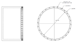
Attached is a sketch of what I'm working with. Locked into these dimensions and this overall design-- not looking for advice on the design itself. Primarily looking for how I can determine if I'm treading into dangerous territory of material failure based on material properties, stress on the threads, and material margin between OD/ID and the threaded hole.
 

Attachments

  • 1746114204719.png
    1746114204719.png
    49.9 KB · Views: 29
Could you include a picture of the component when assembled (define boundary conditions, + bolt preload) to its interfacing structure. Also, can you show in a diagram how the component is loaded.
 
Sure, attached is a section view figure of the overall assembly. My part will be fastened to plate with 1/2" clearance holes and a flange face with lip features that define my ID and OD. Screws shown in blue, flange plate in orange and my part grey. The plate will have an oring to seal off the assembly and I'll pressurize the assembly to at least 20 psi. With an ID of 23.705" I'm looking at an axial force on the system of about 8,827lbs. Between 26 screws I'm looking at 339.5 lbs per fastener. Grade 8 screws, lubed with an anti-seize lubricant and torqued to 80 ft-lbs (just pulling this from a standard torque chart). Was going to try and use a mild steel like A36, but if I could justify that an aluminum alloy like 6061 w/ helicoil inserts be sufficient the weight savings would be appreciated.
 

Attachments

  • 1746119125953.png
    1746119125953.png
    22.4 KB · Views: 29
Having a quick look at the assy, and knowing the assy is to be pressurized, the initial thoughts are to determine the interfacing actions of the parts at the bolted joint. You can view your part as a thin walled cylinder connected to a circular plate at the top. The pressure will tend to make the vertical walls of your part move radially outwards. With this action, your bolts can be assumed to restrain this outwards movement, thereby subjecting all your bolts to shear in the radial direction. In addition, with the bolts restraining radial deflection, the walls of your part local to the bolts will rotate, putting all your bolts into bending. First impressions are that your bolts will be subjected to axial tension, radial shear and bending. You can determine these shear and rotation reactions by using the thin walled cylinder tables given in Roark.

Edit 1 - Just thought, by the act of the vertical walls rotating, you may also experience prying loads, as the outer radius at the base will be your abutment location.

Edit 2 - I always remember the saying I first heard decades ago, 'never use friction if it aids you, and only apply if it hinders'. However, that is in my industry.
 
Last edited:
Are you designing the orange part too?

Just use much smaller screws.

26 x 1/2 screws gives you almost 600,000 lbs tension capacity, which is rather more than you need.
 
It seems the stiffness of the joint will not be there. Use shigleys engineering handbook
For the formula. I say because edge distance
Border line. Is there full bolt washer contact?
 
It seems the stiffness of the joint will not be there.
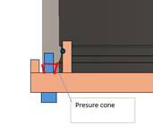
This may be a problem in tightening the bolts. Refer below:

1746161727669.png
The available pressure cone is very small resulting in low stiffness of the body.

The other stresses to be checked(in addition to @Stress_Eng ) are as follows:

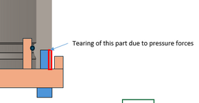
1. The body tearing at the outside surface due to pressure forces
1746162162808.png
2. If the grey and orange components are of different material, differential thermal expansion stresses may arise.


3. Additional sealing force may be required (tapering etc.) near the O ring for effective sealing.
 
This may be a problem in tightening the bolts. Refer below:

View attachment 8950
The available pressure cone is very small resulting in low stiffness of the body.

The other stresses to be checked(in addition to @Stress_Eng ) are as follows:

1. The body tearing at the outside surface due to pressure forces
View attachment 8951
2. If the grey and orange components are of different material, differential thermal expansion stresses may arise.


3. Additional sealing force may be required (tapering etc.) near the O ring for effective sealing.
Ok so it is is drilling into the axial length of the pipe or cylinder wall.

I'm in agreement with goutam here in concentrating on that rather thin strip of metal highlighted in red. Your end plate will have some element of bending involved which will exert a radial force on the end of the bolt which then causes a bending moment on the bolt. The fatigue risk of this and consequential cracking of the hole looks likely to me.

I strongly suspect what you will need or should do is add a 1" deep collar to the main pipe at the end to restrain the radial forces and prevent thread pull out. so essentially increasing the wall thickness at the area where the bolts are to maybe 1.5 to 2" WT.

A pressure of 20psi may not sound much, but you have a lot of square inches. I get close to 4 tonnes force on that end plate. Think of two cars hanging off the end of it....
 
In addition to the local stresses that want to burst the wall next to the thread and crush the face of the tube right there, I would study the deformation of the tapped threads themselves. Under torque and load, threads of a tapped hole or nut do expand, particularly the first couple threads. So I would perform an axisymmetric FEA of just one segment including one bolt and its threads and confirm that the radial expansion at the tapped hole threads remains a small portion of the thread pitch. In other words, confirm the tapped hole doesn't open up and cause the threads to strip.

It's perhaps helpful that your gasket appears to be radial and inboard because this bolting design is going to produce rather uneven clamping force. If you move to a design that requires preload across the contact area between the flange and tube that's an additional criteria.

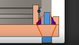
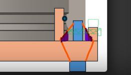
I agree with Goutam to think about the pressure cone (or pressure ellipsoid) philosophy however its my understanding that the pressure cone is widest at the flange face. If the facing is not wide enough to support the full width of the pressure cone, local distortion and stresses amplify. I've sketched the pressure cone in orange and the purple is unsupported area within the pressure cone.

Pressure Cone.png
 
Given that this is essentially a plug which is being held in, why don't you use the upstand flange which is already there and hold the plug in with a set of pins in shear into the whole of the wall thickness??

You could probably tap the up stand flange element to make the pins flush.

See below in green - possibly a bit hard to see... And ditch the blue bolt. You might need double the number but at least there is only shear to worry about?

alternative.png
 

Part and Inventory Search

Sponsor