greenimi,
I'm not a politician, and I don't dodge direct answers - at least not when it comes to this topic. The reason why you don't accept my answer and repeat your question, is that you've made a presumtion that you refuse to let go although I challenged it.
As I said and repeated: " a theoretically more exact way to achieve that would be to make them contact the datum features simultaneously ". In other words, there should be no condition in which one component of the common datum feature simulator has stopped contracting and the other one is able to keep contracting. They need to come into contact with the two separate portions of the physical common datum feature simultaneously.
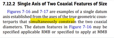
I will give you an example, but first I want to remind you the goal. The goal is to "... simultaneously constrain ..." as outlined here:

The exact technique is not the goal itself, it is secondary to the goal and should attempt to realize it.
Now the example:
Suppose each of the coaxial (per design) shaft portions designated and referenced as a common datum feature A-B are dimensioned by dia. 10+/-0.1 and toleranced as a 2X pattern by a datumless position of 0 at MMC. And suppose that in reality they came out almost perfectly aligned (the measured position error is 0). But one came out at dia. 10.05 while the other at dia. 9.9.
If both coaxial components of the simulator start contracting from the MMB of 10.1, then to come at contact with the actual datum feature at the same time, they should be contracting during the same time-window ("simultaneously" as the standard specifies in
7.12.4 Pattern of Features of Size RMB), but at
different rates.
If you accept that this is what should happen or at least that there should be an attempt to achieve that, then, your question about what happens to one contracting cylinder when the other stopped becomes irrelevant.
Now the above may sound technically complicated and mfgenggear may say it is a "PITA"

,

, but we all know that RMB (and RFS) is always more complex to inspect than MMB (and MMC).
As for the single solution,
In the thread I linked to you'll find a snippet made by SeasonLee from a pretty good explanation by
GeoTol about the constrained least squares, which is the new stabilization procedure for a rocking datum, and that is exactly what you asked about. I still don't own a copy of the latest math standard, but I have seen this method mentioned only in the context of planar datums. However as far as I understand it, I don't see a reason why the same principle can't be used to accomodate the establishment of a common datum from a pattern of features of size.
I also like the technique provided in SeasonLee's
GeoTol reference in the more recent thread (where this discussion originated) utilizing the two Unrelated AMEs to obtain separate axes, and then deriving a circumscribed cylinder containing these two unrelated axes, which in turn provides a new common datum axis. It could probably be incorporated in CMM calculation algorithms (may be already).
My own way to tackle this would be to simply say that the common axis should be established by two Related AMEs, which are "Related" not because of any preceding datums in the datum reference frame, but because, although forming a primary true geometric counterpart, they must be perfectly coaxial to each other.

