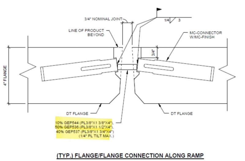
Those varying plate thicknesses are strange (to me) for the following reasons,
1. There’s no info on the plate spacing nor info on where the various plate thicknesses are to be installed.
2. These plates are required primarily to transfer diaphragm shear which I assume to be an approximately constant value (pounds per foot of diaphragm depth). Constant shear = same required shear strength per connection. To some extent the detail also helps limit differential deflection between the double tees - however based on the weld detail I'm not sure how increasing the plate thickness can be quantified to help compute reduced differential deflection. My experience it that we space the connectors at 4’ oc within the middle third of the span and at 8’ oc elsewhere.
3. The weld seems to be the governing limit state. (So why are different plate thicknesses required if the indicated ¼” fillet weld dictates the connection strength?)
4. The indicated plate thicknesses are significantly thicker than I’ve ever seen for this detail.
Can you call whoever drew this detail and ask them?
EDIT: Upon further review I realized that that plates are all 3/8" thick. 3/8" plates are what are most commonly used. Different widths are provided to accommodate differing gaps between the tees. I suppose the fabricator knows from experience that providing a mix of different width plates as shown will accommodate most field conditions.

