×
INTELLIGENT WORK FORUMS
FOR ENGINEERING PROFESSIONALS

Log In

Come Join Us!

Are you an
Engineering professional?
Join Eng-Tips Forums!
  • Talk With Other Members
  • Be Notified Of Responses
    To Your Posts
  • Keyword Search
  • One-Click Access To Your
    Favorite Forums
  • Automated Signatures
    On Your Posts
  • Best Of All, It's Free!

*Eng-Tips's functionality depends on members receiving e-mail. By joining you are opting in to receive e-mail.

Posting Guidelines

Promoting, selling, recruiting, coursework and thesis posting is forbidden.

Students Click Here

Questions about HEX mesh
2

Questions about HEX mesh

Questions about HEX mesh

(OP)
Hello,

I hope you are doing well.

I have some questions concerning HEX mesh. My idea is to mesh a pin with HEX elements. I divided the fairly simple geometry into three cylinders, so it can be easily HEX meshed (without using the HEXMesh Bodies feature of FEMAP). I'll leave an image of the geometry below.
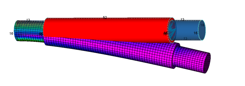


The problem is that the central cylinder cannot be meshed (I think it is because a circle line in the outer surface so it has a coincident mesh with the two outer cylinders). Actually, it turns red and FEMAP says it cannot be HEX meshed but nonetheless it gives a really nice mesh with which I can run an analysis.

So my questions are :
1. Is it normal that even if it turns red I can use the resulting mesh for an analysis ?
2. Why does FEMAP say that it cannot be HEX meshed but provides a nice mesh ?
3. What is the difference between the commands HEXMesh Solids (Mesh -> Geometry -> HexMesh Solids) and HEXMesh Bodies (Mesh -> HexMesh Bodies)? I know that HexMesh Bodies is "simpler" to use. It directly provides a HEX Mesh for a solid, but what is the main difference with the HexMesh Solids command?

Before starting the mesh I watched one of the many cool videos provided by Blas Molero about HEX Meshing (https://www.youtube.com/watch?v=nQwkSa8DXGo). Kudos and thanks Blas for all your valuable help.

And thanks in advance for the replies to this post.

Cordially,
EC
Replies continue below

Recommended for you

RE: Questions about HEX mesh

Dear EC,
Without the FEMAP model in hand is difficul to know the real proble, in the details is the devil!!.
Post your FEMAP model here and we can take a look to it.
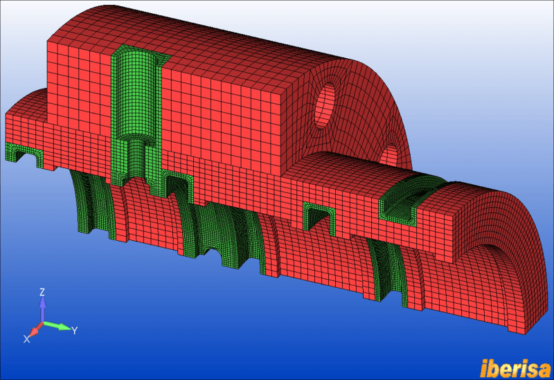
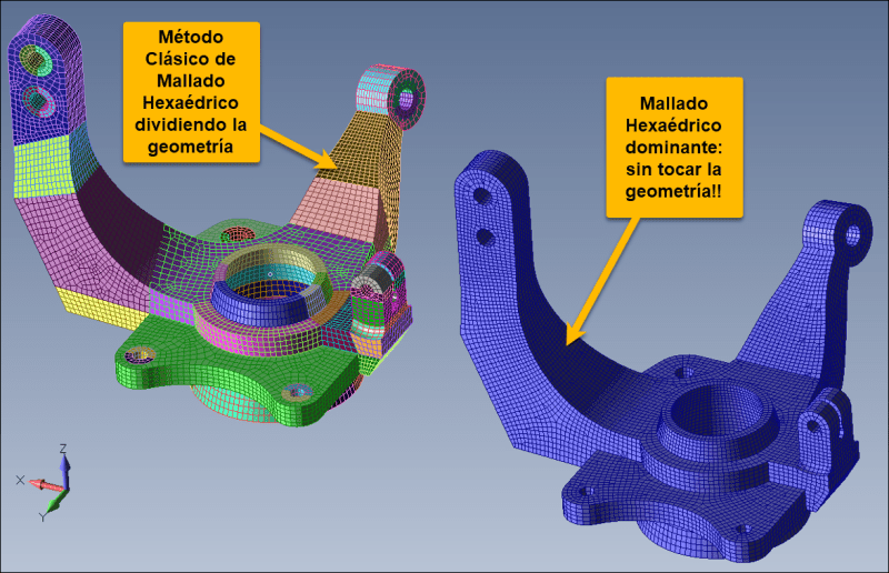
The difference between HEX MESH BODIES and the classical HEX mesh command is clear: only regular solids can be meshed.
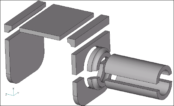
Femap can only hex mesh “extrudable” solids, therefore if you have a part that is more complex, you must break/slice it into multiple, simpler solids that can be meshed. While we use the word “extrudable” here, the actual solids that Femap can mesh are much more complex than simple, straight extrusions.
During the process of hex meshing sizing, Femap identifies the base and top surfaces and automatically matches (slaves) the mesh on the two surfaces. This is required for successful hex meshing. The base and top surfaces must produce the same surface mesh, not necessarily the same shape, but the same number of nodes and elements with the same connectivity.


If a body is getting red, bad plan, not hex meshing is possible.
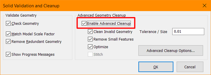
Before applying any mesh sizing run command GEOMETRY > SOLID > CLEANUP of the base solids to make sure the geometry is correct, enabling the advanced cleanup to remove small artifacts or invalid geometry.


FEMAP HEX mesh classical command is very powerful, if you understand how it runs you will be able to create awesome & accurate FE models:


HEX BODY MESH
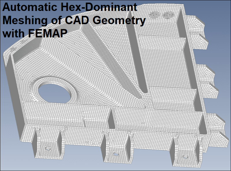
This is the modern command where you can mesh with HEX DOMINANT any solid geometry, not geometry preparation is required but the mesher will use TRANSITION elements like TET, PYRAMID & WEDGEs, but in low number. Is simply doing a clik in the solid body and done!!


Best regards,
Blas.

~~~~~~~~~~~~~~~~~~~~~~
Blas Molero Hidalgo
Ingeniero Industrial
Director

IBERISA
48004 BILBAO (SPAIN)
WEB: http://www.iberisa.com
Blog de FEMAP & NX Nastran: http://iberisa.wordpress.com/

RE: Questions about HEX mesh

Hello, ecFem.
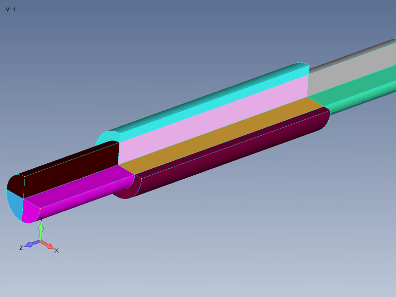
Your geometry look fairly simple. You need to make a couple additional slices to decompose geometry into simple parts. Use Solid Slice->Using Curve to slice middle cylinder into two collinear cylinders.
Here is my proposal how to divide it into hex meshable parts. 1/4 part of shaft is hidden for clarity. Different solids have different colors.

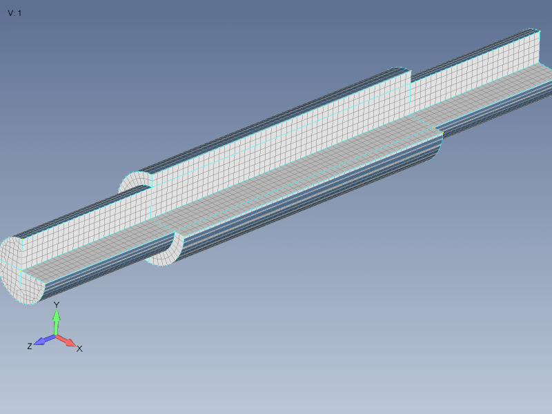
Now I can set mesh size using Mesh->Mesh Control->Size on Solid and than mesh using Mesh->Geometry->HexMesh Solids.

Now as solids are properly hexmeshed there are no solids highlighted in red.
Hope this will help.

Red Flag This Post

Please let us know here why this post is inappropriate. Reasons such as off-topic, duplicates, flames, illegal, vulgar, or students posting their homework.

Red Flag Submitted

Thank you for helping keep Eng-Tips Forums free from inappropriate posts.
The Eng-Tips staff will check this out and take appropriate action.

Reply To This Thread

Posting in the Eng-Tips forums is a member-only feature.

Click Here to join Eng-Tips and talk with other members! Already a Member? Login


News


Close Box

Join Eng-Tips® Today!

Join your peers on the Internet's largest technical engineering professional community.
It's easy to join and it's free.

Here's Why Members Love Eng-Tips Forums:

Register now while it's still free!

Already a member? Close this window and log in.

Join Us             Close