×
INTELLIGENT WORK FORUMS
FOR ENGINEERING PROFESSIONALS

Log In

Come Join Us!

Are you an
Engineering professional?
Join Eng-Tips Forums!
  • Talk With Other Members
  • Be Notified Of Responses
    To Your Posts
  • Keyword Search
  • One-Click Access To Your
    Favorite Forums
  • Automated Signatures
    On Your Posts
  • Best Of All, It's Free!

*Eng-Tips's functionality depends on members receiving e-mail. By joining you are opting in to receive e-mail.

Posting Guidelines

Promoting, selling, recruiting, coursework and thesis posting is forbidden.

Students Click Here

DC motor nameplate decoding
2

DC motor nameplate decoding

DC motor nameplate decoding

(OP)
Hi,
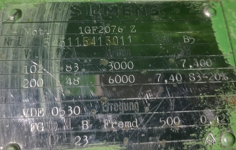
we have some old Siemens DC motors that have nameplates like the following (see attached image), here I state some of the stats:

CODE -->

102V 83A 3000rpm 7.4kW
200V 48A 6000rpm 7.4kW S3->20%
Field:
500V 0.42A 
We are looking for appropriate DC drivers. I have some trouble understanding the nameplate.

1. Does it mean the max armature voltage is 200V at which the power is 7.4kW and 6000rpm?
2. Is the min voltage 102V or is that just the voltage of max torque since power is 7.4kW and speed 3000? So, the power from 3000rpm to 6000rpm is constant?
3. What is min armature voltage (below 102V)? I presume there is a drop in power (speed and torque) under 102V?
4. What is max armature voltage? IS 200V the limit or it can be driven above that, does power degrade?

Thanks for all the answers!

Best Regards!


Replies continue below

Recommended for you

RE: DC motor nameplate decoding

Quote:

4. What is max armature voltage? IS 200V the limit or it can be driven above that, does power degrade?
It depends.
Speed and load.
If the motor is allowed to overspeed, centrifugal force may throw the windings out of the armature slots.
It the motor is heavily loaded, the commutator may flash over. That is called by some;
"Ringing the Com'"
Or, something else may break.
If the field voltage is lower, the motor will run proportionately faster at a given armature voltage. (But with less torque.)

--------------------
Ohm's law
Not just a good idea;
It's the LAW!

RE: DC motor nameplate decoding

The DC motor produces torque from the interaction of two magnets - one stationary (the main field) and one moving (the armature). The stronger the magnet, the slower the machine rotates and the higher the output torque.

What that particular nameplate is telling you is that the machine has a continuous rating AND a short-time rating. For continuous operation, the armature requires 102 V at 83 A to produces the design torque at 3000 rpm.
The design is also capable of periodic overloading (S3 duty): armature sees 200 V and 48 A at speeds of 6000 rpm.
In both cases the main field is held constant at 500 V and 0.42 A.

Minimum Voltage
With a fixed field strength (i.e. constant field current), the DC machine produces constant torque over the range from zero to rated voltage. Rotational speed will be proportional to the voltage applied (once you get above the back EMF voltage of the machine which should be in the 15-25 V range). Regardless of the voltage applied to the armature, the current must be regulated to be no more than the nameplate (83 A) value. And therefore the power draw (kW = V x A) will also vary linearly over the range.

Why does the second (S3) rating rotate faster? It has a lower armature current, which means a lower magnet strength.
How long can you operate at the S3 rating? You'd need to understand what "periodic duty" really means. Essentially, the machine is never allowed to run long enough to get to max operating temperature (what you'd see in the 102 V - 83 A case), but it is ALSO never allowed to drop back to ambient temperature between the instances of "peak" loading (200 V, 48 A). The "20%" designation means that the S3 peak operation has to occur less than 20% of the time: i.e. no more than 12 seconds out of every 60.

Operating above 200 V
If you try to operate at a voltage higher than 200, chances are pretty good you will create an arc at the commutator. This is because the voltage between individual bars will be enough to "jump the gap" between them, AND you'll be moving at a faster surface speed (because you'll have had to proportionally lower the armature current, creating a still weaker magnet). At high speeds and/or high voltages any minor imperfections in the commutator/brush interface become magnified - with a higher likelihood of damage. The rotor is designed to operate at speeds up to 6000 rpm (with some safety margin). Over time, the ability to safely operate at high speed is degraded as the material used as a "retaining ring" for the windings and/or commutator degrades - leading to eventual mechanical distortion and ultimately catastrophic failure.

Converting energy to motion for more than half a century

RE: DC motor nameplate decoding

I have a bit of a problem with some of your explanations, G8blu.
Current is very closely proportional to load.
At a given field and armature voltage, the load determines the current.
Back EMF is not 15-20 Volts.
The back EMF is related to field strength and speed of rotation.
With an unloaded motor, the back EMF is very close to the applied voltage.
If a motor is over-driven, the back EMF will rise to above the applied voltage.
The current will drop to zero when the back EMF equals the applied voltage and will increase in the opposite direction when the back EMF rises above the applied voltage.
The motor has now become a generator.
Typically there may be only a few RPM or a few Volts difference between a motor and a generator.

Operation at 6000 RPM and 43 Amps.
The torque of the load must be reduced as well as the voltage being increased.
If the motor is running at full load, and the voltage is increased, the motor speed will increase but the motor current will also increase into the overload range.
Operation at 6000 RPM must be accompanied by reduced torque demands of the load.

--------------------
Ohm's law
Not just a good idea;
It's the LAW!

RE: DC motor nameplate decoding

Anecdote alert:
In the common area of a teaching facility, we had on display an old DC generator.
I am guessing about 100 KW. The nameplate was missing as was the original steam engine.
To demonstrate to the class both back EMF and the interchangeability of most DC motors and generators I decided to try to run the old machine.
We had a couple of work benches with power supplies.
From one bench we were able to supply enough current at 110 Volts to energize the field.
From the other bench we sourced a variable DC voltage.
After rolling the machine by hand to bring up the oil into the bearings, we applied a voltage to the armature.
We only had about 2 Amps available and so could only supply 1 or 2 volts.
The machine started to slowly rotate.
As the speed increased, the back EMF started to develop and the current dropped.
I was able to slowly increase the voltage as the speed and the back EMF increased.
We eventually got the old machine rolling over at a good clip.
It was starting to bounce a little.
That's when a student tripped over our extension cord and both work benches released the magic smoke.
ps: The next lesson was an explanation of collapsing magnetic fields and inductive kick.

Strike when the iron is hot?
or
Strike when the diode is not!

--------------------
Ohm's law
Not just a good idea;
It's the LAW!

RE: DC motor nameplate decoding

Bill: You're correct - back EMF is NOT 15-25 V. What I meant to say was that the DIFFERENCE between back EMF and applied voltage is in that range, pretty much independent of actual current loading.

A typical speed/voltage curve for a DC machine shows two intercepts: 0 V at ) rpm, and rated V and rated RPM. This is not technically correct, because there is a small voltage drop in the winding. What this means is that the curve has to intercept the voltage axis at something other than 0 at zero rpm, then exhibit a step change to some speed at a very low voltage.

Torque is a function of power and speed. If the speed goes up and the power stays constant, the torque drops. If both power and speed go up (proportionally), torque remains constant. The motor nameplate in question indicates that the machine can draw constant current (up to 83 A)as voltage increases from 0 to 102 (i.e. rated volts). What this really means is that torque is constant from 0-3000 rpm, because power (V x A) is increasing proportionally with speed. After that point, the limit on current goes down (presumably more-or-less linearly with speed) as voltage continues to increase (up to 200 V) such that at 200 V the limit is only 43 A ... which equates to having a constant power output of 7.4 kW from 3000-6000 rpm ... which in turn turn means a decreasing torque profile over that range.

Converting energy to motion for more than half a century

RE: DC motor nameplate decoding

(OP)
Thanks for all the answers!

Quote (Gr8blu )

In both cases the main field is held constant at 500 V and 0.42 A.
Does that mean this motor does not support variable field, it must be constant?

Quote (Gr8blu )

ALSO never allowed to drop back to ambient temperature between the instances of "peak" loading (200 V, 48 A).
So the motor must not be "cold" for it to run in S3? I suppose there should be a temperature sensor on armature wired up to the motor driver? (in this case there isn't one).

RE: DC motor nameplate decoding

Belezg: With regard to your last two questions, think about things for a minute.

Does the motor support variable field?
The simple answer is yes (for the motor) - AND possibly no (for the controller).
The purpose of field weakening (i.e. operating at less than full field current) is to increase speed. This comes at the expense of torque output, so how much faster can you go and still provide sufficient torque to the process? Most typical process are centrifugal loads (fans, pumps, etc.) which often require MORE torque at higher speeds.
One of the methods of protection recommended for a DC machine is called loss of field. What this really means is there should be a lower current setpoint on the field control that says if my field current is below the limit, please shut down so that an overspeed event does not occur. The "full field" condition for this machine is slightly less than half an amp. How sensitive is your current sensor loop (including any error range)?
Then again - how much faster do you need to go? There will be an upper (mechanical) limit on speed where the machine can no longer hold itself together and will self-destruct - potentially injuring someone nearby.

Temperature and the S3 rating
The reason for the wording "...never allowed to drop back to ambient temperature between instances..." is that it represents a worst-case scenario. Most processes don't ever come to a dead stop - they tend to idle along at a reduced output between flurries of more intense activity (think sitting in a car at a red light with the engine running). If the current isn't low enough - or the idle period long enough - the electric motor won't get rid of all the heat built up from the peak operating portion of the cycle. If that's the case, then the machine components never get back to ambient temperature. So if the heat build-up starts from something other than "cold" (i.e. ambient), we've already used up some of the thermal capability and thus cannot push the machine quite as hard (or as long) before hitting the upper thermal limit.
If however you DO have a process or cycle that allows sufficient idle time to get back to ambient, the machine will thank you for it by operating for a longer period before failing due to thermal issues.

Converting energy to motion for more than half a century

RE: DC motor nameplate decoding

Quote:

back EMF is NOT 15-25 V. What I meant to say was that the DIFFERENCE between back EMF and applied voltage is in that range, pretty much independent of actual current loading.
An explanation of Back EMF and load current.
A typical AC induction motor runs just a little below synchronous speed.
For instance for a synchronous speed of 1800 RPM the motor may turn at 1760 or 1740 RPM at full load.
t no load, it will run much closer to synchronous speed.

DC motors;
An armature spinning in a magnetic field may be a motor or a generator.
An armature spinning in a magnetic field will generate a voltage proportional to the strength of the field and the rotational speed.
At a speed slightly above no-load speed, the machine is neither a motor nor a generator.
This is the speed at which the BACK EMF equals the applied voltage.
As a load, starting with friction and windage slows the machine slightly,
As the machine slows, the back EMF drops.
The difference between the supplied voltage and the back EMF is what drives the current through the armature circuit.
As the load is increased, the speed drops.
When the speed drops, the back EMF is less and the difference is greater.
The armature current is mostly limited by the armature circuit resistance.
The resistance of the armature circuit is very low, so a small difference between the applied voltage and the back EMF will drive a fairly large current through the armature circuit.
The difference between the back EMF and the applied voltage will be the applied voltage minus the product of the armature circuit resistance and the armature current.

Operation at double speed:
As the armature voltage is increased, the difference between the applied voltage and the back EMF becomes greater.
Thus the current increases.
Increased current means increased torque and the torque produced is now greater than the torque demanded by the load.
As a result, the motor accelerates, as the motor accelerates the back EMF increases and the current drops.
The motor will increase speed until the torque produced equals the torque demanded by the load.
If the load becomes too much, the motor will not reach a speed where the current drops to or below rated current.

Why is the current limited at higher speeds?
The way to limit current is to limit the load.
50% current implies 50% load.
But why the limit.
The commutator has a current/voltage limit.
Too much armature current and voltage and the commutator may flash over bar to bar.
I saw that once. We were commissioning a very large drag line excavator.
The main hoisting winch was driven by 3000 HP DC motors working together.
We were doing current limit/stall tests.
For these tests we installed jumpers across the brush-gear of the motors to simulate a stall, as a stall is almost a short circuit. (Very low resistance and no back EMF)
Or factory technician made a mistake and over-excited the generator fields.
The commutators all flashed over, or as it is sometimes called, the rank the comm.
It is impressive to see 4 3000 HP generators with rings of fire around their commutators.
That is probably why the current is limited at higher applied voltages.

I don't like to see back EMF or several other motor parameters given as absolutes.
Too may factors interact, and to state a load current, (Actual, not rated), speed or load as absolutes implies assumptions about other parameters that may not be accurate.

--------------------
Ohm's law
Not just a good idea;
It's the LAW!
RE: DC motor nameplate decoding

Voltage limits on commutators: related to the surface speed, the number of bars used, and the straight-line distance between them (at the commutator surface). Current limits on commutators: related to surface speed, number of brushes (and their contact area), and "empty" surface area available.

Reason 1 (voltage)? The ability to successfully commutate (i.e. change polarity of voltage or current). Because the time to reverse polarity is the time it takes one bar to cross the contact area of the brush face - which can easily be shorter than the time it takes to operate a fast-acting circuit breaker. Note that the applied line voltage is divided equally between the commutator bars between one brush polarity and the next - and that the smaller the voltage "step", the easier it is to switch in the short time period.

Reason 2 (current)? Current creates heat when interacting with resistive elements - like the copper of the bar or the carbon of the brush. Too much current and the heat gets to a point where the brush material changes composition (i.e. burns) and/or the film changes to create a higher friction surface. In both cases, it makes it harder to commutate - ultimately leading to sparking at the brush-copper interface.

Every spark - no matter how small - ionizes the surrounding air. Enough ionization and the spark travels farther - possibly to where it can reach a ground plane or something with the opposite polarity. If it does manage to reach the next brush arm around the circumference - the "ring of fire" occurs.

Converting energy to motion for more than half a century

RE: DC motor nameplate decoding

Great question and good response; thanks all.

-----*****-----
So strange to see the singularity approaching while the entire planet is rapidly turning into a hellscape. -John Coates

-Dik

RE: DC motor nameplate decoding

Gr8blu;
For discussion:

Quote (Gr8blu)

Note that the applied line voltage is divided equally between the commutator bars between one brush polarity and the next
No disagreement here.
However, the actual voltage is the applied voltage minus the back EMF.
The highest EMF (and the lowest actual voltage) is midway between the poles.
The lowest EMF (and the highest actual voltage)
is adjacent to the brushes.
This makes sparking brushes particularly serious.
As each segment arcs over, the voltage rises across the other segments.
A commutator will generally withstand some spark carryover from the brushes, but there may be very little safety margin left before the "Ring of Fire".

--------------------
Ohm's law
Not just a good idea;
It's the LAW!

Red Flag This Post

Please let us know here why this post is inappropriate. Reasons such as off-topic, duplicates, flames, illegal, vulgar, or students posting their homework.

Red Flag Submitted

Thank you for helping keep Eng-Tips Forums free from inappropriate posts.
The Eng-Tips staff will check this out and take appropriate action.

Reply To This Thread

Posting in the Eng-Tips forums is a member-only feature.

Click Here to join Eng-Tips and talk with other members! Already a Member? Login


News


Close Box

Join Eng-Tips® Today!

Join your peers on the Internet's largest technical engineering professional community.
It's easy to join and it's free.

Here's Why Members Love Eng-Tips Forums:

Register now while it's still free!

Already a member? Close this window and log in.

Join Us             Close