Wheel Bearing Hub Lateral circular run out
(OP)
I am looking for an example of how to perform a tolerance stack up to check the worst case circular lateral run out.
I am only finding basic 1D stack examples , or 2D gap analysis type problems. Hoping someone could point me to a few good resources.
I have paged through Bryan R. FISCHER Mechanical Tolerance Stack book, but I do not see anything remotely similar to what I am trying to do.
I am only finding basic 1D stack examples , or 2D gap analysis type problems. Hoping someone could point me to a few good resources.
I have paged through Bryan R. FISCHER Mechanical Tolerance Stack book, but I do not see anything remotely similar to what I am trying to do.
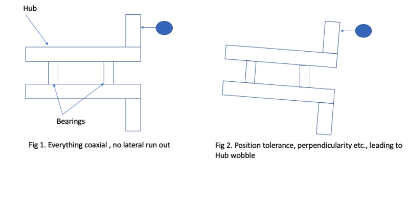
RE: Wheel Bearing Hub Lateral circular run out
My follow-up to the last post is: the circle described by the rolling elements define the axis of rotation, that is the bearing surface of the inner race.
The only bearing runout that affects the hub will be from the moving part of the bearing, and that runout is from the bearing surface of the outer race to the bearing OD.
The fit between the outer race and the hub can be adjusted to maximize or minimize or be in between; there are similar adjustment offset bushings used to change alignment by rotating the bushing.
RE: Wheel Bearing Hub Lateral circular run out
Typically in automotive tolerance stacks are run on statistical packages that account for the distribution of the tolerance rather than just assuming the distribution is just normal or just uniform. I don't think they are incredibly sophisticated, they just Monte Carlo it.
Cheers
Greg Locock
New here? Try reading these, they might help FAQ731-376: Eng-Tips.com Forum Policies http://eng-tips.com/market.cfm?
RE: Wheel Bearing Hub Lateral circular run out
There is a circular run out tolerance call out, of 0.02mm on the face where the dial indicator is shown. I know that bore position tolerance , perpendicularity and other will affect the wobble of this face, but not sure how to compute the stack up. Seems like it would be a fairly common activity for suspension engineers, but I am not finding any examples, besides 2D linear stack up, like this belt tensioner example :
https://www.wasyresearch.com/2d-tolerance-stack-up...
I was told a loop analysis would allow me to find the worst case wobble resulting from the assembly GD&T stack up. But as in the linked example, it doesn't seem to account for the axis of rotation being angled.
RE: Wheel Bearing Hub Lateral circular run out
If you want me to put any effort into this you'd best post a proper drawing.
Cheers
Greg Locock
New here? Try reading these, they might help FAQ731-376: Eng-Tips.com Forum Policies http://eng-tips.com/market.cfm?
RE: Wheel Bearing Hub Lateral circular run out
That's because the axis of rotation being angled doesn't contribute to runout (ie.. it doesn't cause wobble).
Think about it. If the bearings/hub/entire assembly is perfectly manufactured such that runout is zero, but the angle of rotation is angled relative to the axis of the dial indicator, the dial indicator is going to read perfect zeros. The point where the dial indicator contacts the surface being measured does not move.
The only way the dial indicator can read anything other than zero are:
A) the surface being measured moves normal to the axis of rotation. Causes for this in the real world could be errors in flatness of the face, errors in perpendicularity between the face and the axis of rotation, or axial play/runout in the assembly due to bearing problems or insufficient axial preload.
B) the axis of rotation itself is precessing about some other point or axis. Causes for this in the real world are pretty much confined to radial runout in bearings, which for the case of tapered roller bearings are also the result of insufficient preload.
RE: Wheel Bearing Hub Lateral circular run out
You need to calculate the maximum deviation of the axis of rotation (which it seems you have already done) and then use geometry to calculate how that affects the position of the measured point on the rotating face based on maximum axis deviation from nominal plus position changes due to imperfect features.