×
INTELLIGENT WORK FORUMS
FOR ENGINEERING PROFESSIONALS

Log In

Come Join Us!

Are you an
Engineering professional?
Join Eng-Tips Forums!
  • Talk With Other Members
  • Be Notified Of Responses
    To Your Posts
  • Keyword Search
  • One-Click Access To Your
    Favorite Forums
  • Automated Signatures
    On Your Posts
  • Best Of All, It's Free!

*Eng-Tips's functionality depends on members receiving e-mail. By joining you are opting in to receive e-mail.

Posting Guidelines

Promoting, selling, recruiting, coursework and thesis posting is forbidden.

Students Click Here

Risa 3d end moments problem

Risa 3d end moments problem

Risa 3d end moments problem

(OP)
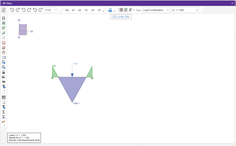
I have a problem with Risa 3d. I am not receiving the expected results. I have simply suported beam and the program is reporting end moment reactions, like it was fixed-fixed. Have you ever experienced that problem? Wha can I do? Plese see attached.
Replies continue below

Recommended for you

RE: Risa 3d end moments problem

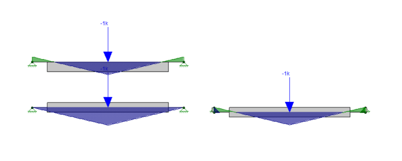
You have a top of member offset on the member, right? That effectively creates a rigid link from them members centerline to the top of the member. The boundary condition (where the pinned boundary condition exists) is at the bottom of that rigid link.

In the image below, I've modeled a simple beam with TOM offsets and without. Then I also modeled one using rigid links instead of the TOM offset.


Caveat:
I worked for the original creator of RISA for 16 years until he sold the company to some European guys with a name that's impossible to pronounce (Numetshuck?). I am in no longer affiliated with RISA in any way. My answers are based on the knowledge that I gained from using their program for so long. Also, I now work for one of their main competitors and cannot be viewed as an impartial observer.

RE: Risa 3d end moments problem

If you are dead-set on using the offset revise one of the supports to be a roller to release the restraint created by the offset.

RE: Risa 3d end moments problem

Why would you use top of member offsets on a single member analysis?

In fact, besides having it visually appealing, why use the top of member offsets at all? It's my opinion that the times where centerline of member analysis wouldn't be appropriate are all times where you'd already know that going in and could easily make the required adjustments to your design and analysis after the fact. It seems I see more questions about weird analysis results coming from the use of t/o member offsets versus the number of situations where using t/o member offsets have saved some sort of catastrophic analysis or design deficiency.

RE: Risa 3d end moments problem

I've never understood why the TOM offset is available.

PRO : The 3D plot will look pretty.
CON : The calculations will be wrong.

If RISA was used for architectural rendering then the PRO would be critical. However RISA is used for design and the CON is devastating. I have always taught trainees to NEVER use it, and showed them why.

This was a simple beam, and so it was obvious the calculations were wrong, but what if this beam was in a larger model? Probably with numerous other TOM offset beams doing god-knows-what to the results. Painful to think about. RISA needs to remove this option.

RE: Risa 3d end moments problem

Quote (Geoff13)

I've never understood why the TOM offset is available.

Oooh, I can answer that one. Long ago (before I worked for RISA), one of their employees (Chris M) wanted RISA to become more "building friendly". He had used both RISA and RAMSteel extensively in his design career. So, when he came to RISA, his goal was to expand RISA's market into the types of buildings that he had frequently worked on. This is why RISA eventually released RISAFloor!

Anyway, the first step in that process (say around the year 2000) was to add other features to the program that were "building friendly". This included member area loads and the Top of Member offset. By the time I got there, I believe we'd all realized that the top of member offset was something of a problem. Eventually, we even contemplated removing the feature because it caused more problems (i.e. confused users with the OP's exact issue) than it solved. But, it was never actually removed. Instead it got wrapped into the more generic "analysis offset". That, IMO, is better. Because it forces you think understand that this offset affects your analysis before you use it.

FWIW, I believe there is also "Member Detailing Information" that can be specified in RISA to specify the type of offsets used for Architectural rendering. This was put into the program (I believe) so that fully information could be retained when importing / exporting from CIS/2 or other such architectural formats. But, that detailing information doesn't affect the analysis results at all.... which is usually what I prefer.

RE: Risa 3d end moments problem

Hi Josh

Long time since we talked, but I know we've both moved on over the years. You helped me understand how RISA worked "behind the scenes" so I could make my models and feel comfortable with the results on some of my non-typical uses of RISA.

It's been long enough since I ran RISA that I'm not familiar with a TOM name change. Certainly the TOM name didn't make it clear that it would change the analysis.

RE: Risa 3d end moments problem

@jayro12

If you only ever model everything CL-CL then you're missing some real internal moment effects. Nothing major, but could be the difference between passing and failing on some members. It basically just saves you the effort of having to manually model every rigid link between all member centroids to make them act properly in your frame. You could always accomplish the same thing with rigid links, as Josh showed, so it's just a time saver.

A classic example of this would be a railing mounted to the side of your member (very common support condition). The rail's gravity loads impart a small torsion on that supporting member, and if you have an open member like a wide flange or channel, that torsion could quickly add up to large stresses and rotations, even for small loads. You can model a rigid link (or even a plate or bolt if there is some discrete support each post) for the railing post to sit on, imparting the torsion, or you can offset the railing a few inches in the properties.

I basically try and keep my primary structural members at CL's so you don't have any weird-seeming results (even if they are perfectly valid, it can get confusing), and offset the other misc, infill and other members to get all the various internal moments modeled. I also love end offsets, which helps limit moments. Between the increased moments of analysis offsets and the reduced moments of end offsets (just another automatically generated rigid element), it may all mostly be a wash, but I prefer to catch these different affects as I can.

RE: Risa 3d end moments problem

Quote (larcix)

your big long post.

I still stand by my statement. Rigid end offsets make sense to me. Top of member offset do not, in my opinion, provide any sort of optimization to the design. And if, as an engineer, you can't recognize the situations where it would be necessary to account for it, then you shouldn't be doing structural design.

Your example was not a top of member offset, it was a horizontal offset, which actually isn't available is Risa besides using a rigid link.

And specifically in the case of the OP's scenario, it is absolutely ridiculous to be turning on the top of member offset.

RE: Risa 3d end moments problem

In response to Larcix concern about modeling beams as only c/l to c/l, I would like to refer to the following thread:
[link https://www.eng-tips.com/viewthread.cfm?qid=501528]

Quote (NorthCivil)

A real common post war method to build around here is:

24 foot wide house, bearing walls down the exterior, with one line of beams/posts up the centre.
...
I was called out to a 3 level house once built this way. The owners wanted to open-concept the basement, so they just removed all the posts. 2 full occupied floors above the basement, bearing down on nothing. the floor was deflecting obviously, about a foot from flush.
...
the whole house, just being held up by the broken floor plate, acting like a kind of tent/shell. the plywood over the joists creating a "net" so to speak.

having seen that, i have no time for arguments like we had here the other day, about how long we should calculate header spans over windows, giving or taking 3".
Red Flag This Post

Please let us know here why this post is inappropriate. Reasons such as off-topic, duplicates, flames, illegal, vulgar, or students posting their homework.

Red Flag Submitted

Thank you for helping keep Eng-Tips Forums free from inappropriate posts.
The Eng-Tips staff will check this out and take appropriate action.

Reply To This Thread

Posting in the Eng-Tips forums is a member-only feature.

Click Here to join Eng-Tips and talk with other members! Already a Member? Login


News


Close Box

Join Eng-Tips® Today!

Join your peers on the Internet's largest technical engineering professional community.
It's easy to join and it's free.

Here's Why Members Love Eng-Tips Forums:

Register now while it's still free!

Already a member? Close this window and log in.

Join Us             Close