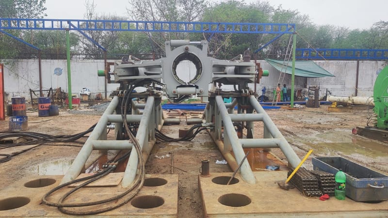
combined stresses on pipe clamp
(OP)
I am trying to calculate the combined stresses on a pipe clamp.
2 forces acting on it.
a) the clamp is in 2 halves , the 2 halves connected with 10 hyd cylinders on top (12'o clock) exerting a closing force of 2000 tons
b) another 2 cylinders connected at 9 o clock and 3 o clock exerting axial force on 750 tons.
c) What wold be the collapse pressure of this clamp
The clamp is 50 inch OD, Yield Stress of Pipe is 60,000 psi and wall thickness is 0.7 inch, lenght of clamp is 80 inches
RE: combined stresses on pipe clamp
Please post a sketch or picture of the situation.
“Do not worry about your problems with mathematics, I assure you mine are far greater.” Albert Einstein
RE: combined stresses on pipe clamp
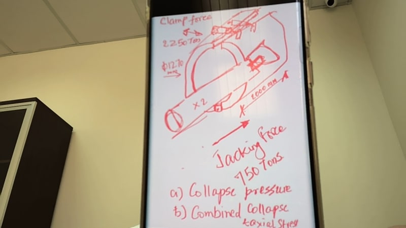
and I have 2 cylinders on either side with a total Pushing force of 750 tons.
My clamp has an ID of 1.27 meters and a length of 2 m.
My clamp if clamping a pipe of :
OD 1.27 m
wall thickness of 17 mm
Yield strength of pipe is 4150 kg/cm2
Need to calculate the
a) Collapse pressure on pipe
b) Combined Collapse and Axial stress on pipe (the clamping and the pushing)
RE: combined stresses on pipe clamp
Looking at the sketch you provide I assume there is a hinge at the base of the clamp??. When the clamp is in operation is there a gap at the top of the clamp such that the clamp faces are not touching? This being the case the clamp will only clamp on the pipe in one spot and will not be an even pressure around the pipe, let’s say the clamp acts on the midpoint of the pipe therefore if you take moments about the hinge of the clamp then the clamping force on the pipe mid section will be 4000lbs. I haven’t got any formula for pipes or pipe clamps under point loading to hand but can you confirm my assumptions that I have made so far.
“Do not worry about your problems with mathematics, I assure you mine are far greater.” Albert Einstein
RE: combined stresses on pipe clamp
The pipe clamping on top, with hinge being diametrically opposite, the moment will be f x d, f = 2250 tons and d is 1.27 m
the thrust cylinder is right in center (750 tons) and along the axis, so i believe the moment from this force may not be there.
Rgds
RE: combined stresses on pipe clamp
What collapse pressure? The thing is open at both ends?
Pressure on the pipe is clamping force divided by area of the clamp no? So 2.8Mpa or 28 bar equivalent? There are collapse formula in offshore pipe codes.
17mm thick on 1.27m is a D/t of 70. Sounds rather thin to me.
But clamps are not quite the same as water pressure so not sure if this is the right way to think about. Might need an FEA analysis. Or a structural man used to clamping pipes / structural pipe on oil rigs and similar.
Remember - More details = better answers
Also: If you get a response it's polite to respond to it.
RE: combined stresses on pipe clamp
I very much doubt that it will grip evenly all the way round 360 degrees, if your clamp is going to work then when the clamp is actuated there should be a gap between the clamp faces at the top.
Do you have a proper drawing showing the pipe clamped in the jaws of the clamp? If the clamp faces at the top have no gap they won’t be clamping the pipe in my opinion.
“Do not worry about your problems with mathematics, I assure you mine are far greater.” Albert Einstein
RE: combined stresses on pipe clamp
I agree with the comments of LittleInch ... However, your incomplete description of the problem compounded by your limited word usage is causing difficulties and most delays of any help from eng-tips.
Are you trying to "crimp" this massive pipe and achieve a pressure-tight seal ? .... Who knows ???... I can't tell..
Can you get someone to help you explain "collapse pressure of the clamp" .... I don't understand this either
It should be pointed out that you have decided to clamp a very thin walled piping system (Do/t = 1270/17 =74)
This, IMHO, is the primary source of your problem...
You state:
"so I have say 10 Hyd cylinders on the top of the clamp with a TOTAL clamping force of 2300 tons
and I have 2 cylinders on either side with a total Pushing force of 750 tons"
Where do these numbers come from ?.... are they just some RA estimate or an MBA opinion ? ....
Where are your calculatons ?
MJCronin
Sr. Process Engineer
RE: combined stresses on pipe clamp
See also the attachment for information.
So I think he or she is interested to know if their pipe will collapse. I would just ask the contractor and check his calculations.
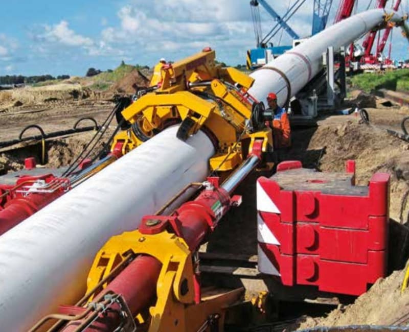
https://www.herrenknecht.com/en/products/productde...
Remember - More details = better answers
Also: If you get a response it's polite to respond to it.
RE: combined stresses on pipe clamp
With very poor word skills, a reluctance to say very much, as well as horrendous drawing abilities, this should only take twenty or thirty more questions !!!
Again, what is meant by "collapse pressure of the clamp" ??.... I don't understand this either
Here is a wild idea .... If indeed, the OP was interested in a "HDD push pull system".... he could say so !!!
Naaaaaaaaaa !!! ..... He has given up on this thread and gone on to other things...
I am going to urge the eng-tips admin to close this thread
MJCronin
Sr. Process Engineer
RE: combined stresses on pipe clamp
The clamping plates of the unit that are lined with special rubber have a sufficiently large contact surface to the pipe. In this way, they keep the contact pressure and the shear stress applied on the pipe low.
RE: combined stresses on pipe clamp
I am overwhelmed by your responses.
pl consider the following for understanding:
a) This is my first ever post on Eng Tips and I shared a part of problem that I was stuck on.
b) I do respond fairly quickly, the difference is the time zone, I am in India and we are 12 hr diff time zone. So all your responses happened in my night time, which I saw today morning at 6 am.
I shall share the full problem and hopefully will get a better solutions from the forum.
Thanks to all for your very valuable posts....
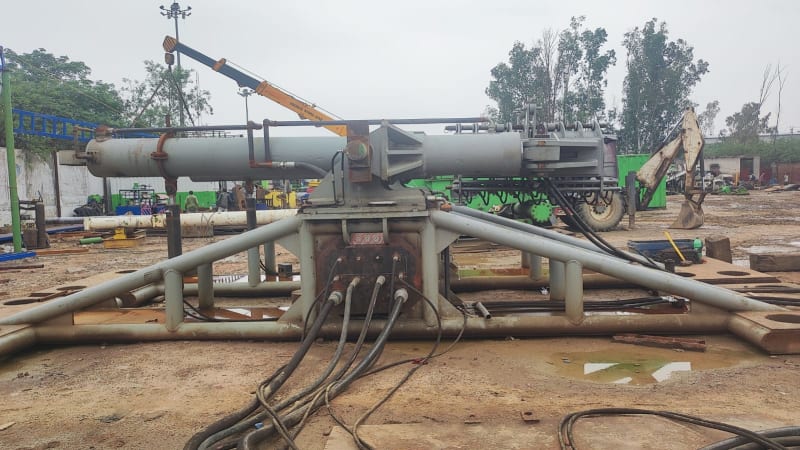
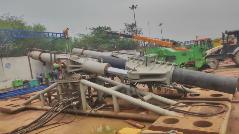
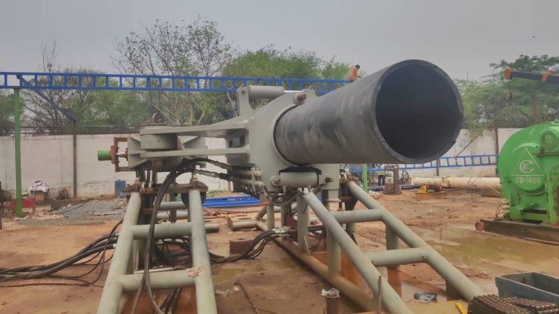
Here i go with my calcs and some better drawings...
Regards,
Vipin Gupta
RE: combined stresses on pipe clamp
excel sheet attached.
this calc passes the 20 inch pipe for 500 tons, but fails on the 50 inch pipe. But from what I was told by Harrenknecht, they are able to safely clamp the 56 inch pipe, X-52 with a wall thickness of 16 mm to a push load of 750 tons and clamp force of 2250 tons.
RE: combined stresses on pipe clamp
Yes, we are designing and fabricating a Pipe Thruster for HDD applications. We have done this for 3 pipes of 20" 24" and 36" and used them successfully.
now we need to push a 50 inch pipe with a low w.t. of 0.7" where the d/t ratio is 71. Besides we need to design for a load of 750 Tons Push.
with a cof of 0.3 , we shall need a clamp force of 2250 tons.
I am afraid that will crumble/collapse/crush the pipe and need help.
Trust, with the photos and the calcs and propoer autocad drawing, I am able to make it clear
RE: combined stresses on pipe clamp
a) Lames equation for d/t<15
Pyp = 2 x Yp (d/t-1)/(d/t)^2
Substituting,
Yp @ 60,000 psi
D/t @ 74 (50"/0.7")
= 1599.7 psi
b) Elastic collapse for d/t > 25
Pe=46.95 x 10^6/(d/t x (d/t-1)^2
= 119 psi
In my case the elastic collapse seems reasonable, but then it does not address the YS of the pipe.
RE: combined stresses on pipe clamp
The one in your spreadsheet is for casing pipes which are already a bit bent.
The Clamp will hold the pipe circular and hence is a bit odd compared to water external pressure. You might need to do something a bit more fancy.
Remember - More details = better answers
Also: If you get a response it's polite to respond to it.
RE: combined stresses on pipe clamp
Does the elastic collapse or equation (in my latest post above) hold good?
RE: combined stresses on pipe clamp
Remember - More details = better answers
Also: If you get a response it's polite to respond to it.
RE: combined stresses on pipe clamp
Thanks
RE: combined stresses on pipe clamp
Remember - More details = better answers
Also: If you get a response it's polite to respond to it.
RE: combined stresses on pipe clamp
I have had a look in formula’s for stress and strain fifth edition by J.Roark & Young and all I could find was a thin ring under uniform external pressure see page 556 case 19.
That’s the nearest I have found however has I stated earlier the pressure from the clamp will not be uniform because of the gaps in the clamp pads and also because of the hinge at the base of the clamp, in addition to that the clamping force supplied by the cylinders is based at the top of the clamp also adding to a non uniform clamping pressure.
So I would base my design on uniform pressure and then do some testing to be sure my design worked.
“Do not worry about your problems with mathematics, I assure you mine are far greater.” Albert Einstein
RE: combined stresses on pipe clamp
thanks for ponting to Roark book. I got the seventh edition
Substituting my clamp values for dia 1270 and w.t. 0f 17.78 mm,
the Q (Stress) = -1316 Mpa (-ve for external stress) for long tube and 7.5 Mpa for short tube.
This must be the value of what this cyl will take max, before yielding.
my clamp stress calculation for 2250 Tons at dia of 1270 mm length of 2 m is coming to 2.5 Mpa
I guess, the short tube clamp length shall be applicable and the allowable stress is acceptable.
But as Littleinch recommended, best way to find out is by destructive testing only.
Regards
RE: combined stresses on pipe clamp
Something wrong with your units as there is far too much difference here and I can't believe the long tube will withstand 13,000 bar....
q to me looks like external pressure, not stress.
Remember - More details = better answers
Also: If you get a response it's polite to respond to it.
RE: combined stresses on pipe clamp
E/4 x t3/r3 x 1/(1-v2)
where E if 210000 Mpa
t is 17.78 mm
v is 0.3
r is 638 mm
answer is 1.26 Mpa for long tube.
and 7.57 Mpa for short tube, (if the ends are held circular)
have taken l = 2000 mm (my clamp length)
RE: combined stresses on pipe clamp
So it looks like you have a decent FOS to me, but only a physical test will tell you.
Remember - More details = better answers
Also: If you get a response it's polite to respond to it.
RE: combined stresses on pipe clamp
Shout out to all for making this valuable.
by the way, I am hoping to use this clamp to do Direct Pipe by substituting the HK thruster with my designed and fabricated thruster.
we have a project of installing 50 inch pipe x 700 meters under a river. I dont have budgets to buy HK and hence am taking the risk to make my own.
Am confident especially since I have made a few of them, but only for smaller pipe and smaller thrust force.
This one is going to be for 750 Tons of Thrust and hence was wanting to ensure that I do not miss and mess!!
if and when this comes to Fruition, I shall share with you all.
Till next time....
RE: combined stresses on pipe clamp
Yes I think the short length is probably more applicable for your case and like Littleinch says the clamp should keep the pipe circular to some extent. Yep agree with Littleinch on a good factor of safety and some physical testing.👍
“Do not worry about your problems with mathematics, I assure you mine are far greater.” Albert Einstein
RE: combined stresses on pipe clamp
Remember - More details = better answers
Also: If you get a response it's polite to respond to it.