×
INTELLIGENT WORK FORUMS
FOR ENGINEERING PROFESSIONALS

Log In

Come Join Us!

Are you an
Engineering professional?
Join Eng-Tips Forums!
  • Talk With Other Members
  • Be Notified Of Responses
    To Your Posts
  • Keyword Search
  • One-Click Access To Your
    Favorite Forums
  • Automated Signatures
    On Your Posts
  • Best Of All, It's Free!

*Eng-Tips's functionality depends on members receiving e-mail. By joining you are opting in to receive e-mail.

Posting Guidelines

Promoting, selling, recruiting, coursework and thesis posting is forbidden.

Students Click Here

Pretension truss matrix (direct stiffness method)

Pretension truss matrix (direct stiffness method)

Pretension truss matrix (direct stiffness method)

(OP)
Hi all,

Right now I'm working on a mechanical mechanism where nodes are connected via "spring beams". This is very comparable of doing planar truss analysis, but now the deformations are large compared to the system.

In my analysis, one of the nodes undergoes a predefined deformation, and the rest of the free nodes are moving accordingly, which is calculated via the well known {f} = [K]{d}, where K is the global system stiffness matrix, and d is the displacement vector. Hereby: [K] = [T]^T [K_loc] [T]
When all displacements are known, {f} = [K]{d} is used again to calculate all corresponding forces. I'm interested in the force needed (in x,y-direction) of the node which got the predefined deformation. Because the deformations are relatively high, this process is done incrementally.

Now, I want to include a pre-tension in the mechanism. As trivial as it sounds, I didn't find much information about that in various papers.

From intuition, I would suggest that the total force in the nodes is just a summation of f = [K]{d} and the global pretension vector: {f_ext} = [K]{d} + {f_int}, where f_int is the global pretension vector {f_int} = [T]^T {f_loc}. However, the global stiffness matrix should be modified by the pretension, since the pretension makes the whole mechanism stiffer. But using the aforementioned reasoning, this is not happening.

Therefore, I'm wondering if I make any mistake in this reasoning. Any help would be greatly appreciated.
In addition to that, any tips about papers/books involving pre-tensioning using the direct stiffness method would be very helpful.

Thank you in advance!
Replies continue below

Recommended for you

RE: Pretension truss matrix (direct stiffness method)

I'm sure a picture would help explain your problem

"Hoffen wir mal, dass alles gut geht !"
General Paulus, Nov 1942, outside Stalingrad after the launch of Operation Uranus.

RE: Pretension truss matrix (direct stiffness method)

(OP)
I'll clarify it with some pictures. Thanks for the suggestion.
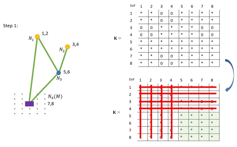
In this example, we can neglect the iterative process. Now, we only deal with one iteration (one step in the grid to the right).

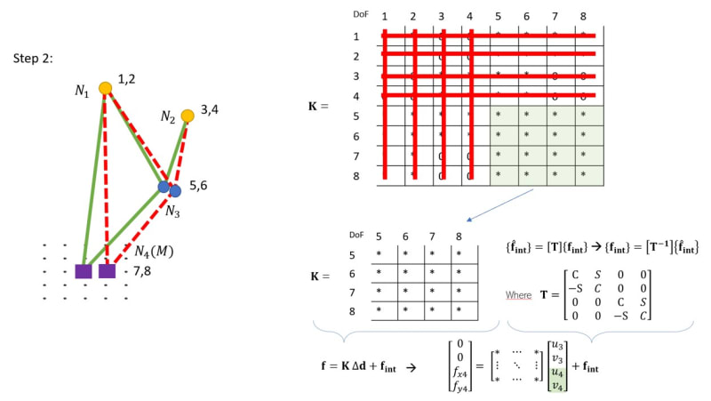
In the first step, the global system stiffness matrix is determined. The relevant part is used to calculate the displacements of the free nodes when the purple node is displacement one "gridpoint" to the right:


Now, I'm able to calculate for the displacement of the free nodes, for which the pretension (f_int) is included:


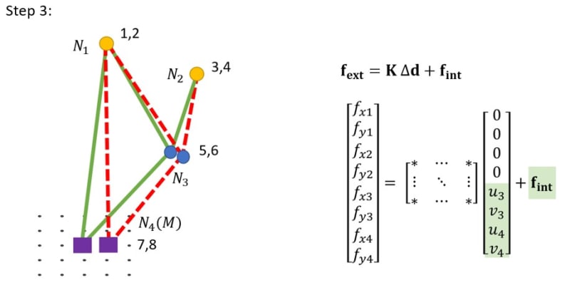
Now I'm able to calculate for all forces: for the fixed nodes as well as for the purple node. The latter is of interest.


RE: Pretension truss matrix (direct stiffness method)

Part of using the F = k u Equation is a mandatory step where you set the constraints.

You can constrain the system by for example setting deformation degrees of freed deformation to zero inside the U vector.

The next step is remove the rows and columns corresponding to those 'zero' displacements from the entire matrix system of equations, a step one could call sub-partitioning.

Well it is a common problem (at least in structural analysis) to have a prescribed initial displacement at a support, and then to determine the resulting forces on the constrained DOFs.
You solve this problem is basically the same way as if the constraint deformation was equal to zero.

I would look towards a matrix solution for a beam or truss that includes support settlement as a good starting point for your problem.


RE: Pretension truss matrix (direct stiffness method)

by "pre-tension" I think you mean ...
anticipate a deflection (of N4) in the +ve x direction
so deflect N4 in the -ve x prior to the loading.

If so, what does this physically mean ?

A way I can see to "pre-load" the structure would be, having assembled the structure, to then shorten one (or more) links (physically this would be done with a turn-buckle).

I don't follow your concept. if N4 is "pre-loaded" by a deflection in the -ve x direction, ok, well and good. This will create a set of internal loads. If you then apply a +ve x deflection to N4, won't it travel through it's starting point (relieving these "pre-loads") and carry on to wherever it'd go if you applied a deflection from the original starting point ?

"Hoffen wir mal, dass alles gut geht !"
General Paulus, Nov 1942, outside Stalingrad after the launch of Operation Uranus.

RE: Pretension truss matrix (direct stiffness method)

(OP)
Sorry if I'm not completely clear.

So in fact I measure the force (in x,y-direction) at the purple node (N4) to hold the mechanism at that specific place (this is what I'm interested in). With pre-tensioning, the location of N4 does not change, but the location of N3 can change (due to the pretension), because that's the only free node in this mechanism.
After I applied the pretension, I shift N4 one gridpoint to the right. Again, the motion of this node is predefined and won't change if the beams would have other stiffnesses/prestress. The only thing I'm interested in is what force is needed (at N4) to displace the mechanism as such.

In short, I measure what force is needed (in x,y-direction) to have that purple node (N4) at every point on the grid. This works well without pre-tensioning the beams, but the results seem weird if a add a pretension the way I do it now.

I have got the idea that I need both a material stiffness matrix and a geometric stiffness matrix, and add them up to use it as my "final" stiffness matrix.

RE: Pretension truss matrix (direct stiffness method)

clearer, but not clear !

why do you want to apply a force to hold the mechanism is place ?

where is N4 with no loads applied ?

How do you change to position of N3 without affecting the position of N4 ?

Are you saying that this is some sort of spring ? So that statically (relaxed ?) N4 is at some location,
but then you move N4 so that the structure fits without some other structure ??
and you want to know the stiffness of this compressed structure ??

"I have got the idea that I need both a material stiffness matrix and a geometric stiffness matrix, and add them up to use it as my "final" stiffness matrix."
you'll have to explain what you mean.
"material stiffness matrix" ... so not "E" ? (ie not metal, but composites) ... this is usually expressed in local (element co-ordinates)
"geometric stiffness matrix" ... this is like EA/L, but with components in global axes (and so constantly changing in your model).

You're looking for the force to move N4 form 1 point to any other of your 25 points ?

"Hoffen wir mal, dass alles gut geht !"
General Paulus, Nov 1942, outside Stalingrad after the launch of Operation Uranus.

RE: Pretension truss matrix (direct stiffness method)

if I understand you right, then statically (with zero load) N4 is somewhere away from your starting position (at 0,0, yes?)
let's say that statically N4 is at (1,0) ... so you apply a force in the -ve X direction to get N4 at (0,0) ... yes?

now if you apply some other force to N4 and it moves, then the internal loads will be just the sum of the two moves, the sum of the forces applied to N4.

as a load I don't like enforced displacements, and would rather apply X or Y loads to N4, to determine how N4 moves (non-linearly), then fit these movements into your grid.

"Hoffen wir mal, dass alles gut geht !"
General Paulus, Nov 1942, outside Stalingrad after the launch of Operation Uranus.

RE: Pretension truss matrix (direct stiffness method)

(OP)
Yeah, your way of reasoning seems right indeed, @rb1957.

Quote (as a load I don't like enforced displacements, and would rather apply X or Y loads to N4, to determine how N4 moves (non-linearly), then fit these movements into your grid.)


I was indeed thinking of that as well...instead of enforcing a certain node to a position, I might better apply the pretension, so that the structure deforms.

After that, I can do two things:
1. Apply certain forces in both directions and determine how the structure deforms.
2. Require that node N4 must be placed in a certain position, and iteratively apply forces on that node to get it there.

RE: Pretension truss matrix (direct stiffness method)

I suspect things are highly non-linear so working with displacement may be better, in this case.

when you position N4, you know the strain (and stress and load) in member 14, but the position of N3 is "up for grabs" .... determined by the minimum strain energy in the other three members of the truss.
this will give you loads in these three members, and you can check the load balance at N4 and the overall balance of the structure at nodes N1 and N2 (of course you can check the load balance at N3 as well).

if you apply force at N4, you know actually very little about the structure (as N4 is assumed to move significantly) but you could solve iteratively ... develop internal loads for the starting position, apply the strains, and move nodes accordingly, and then resolve. repeat ad nauseum. And all this for a position of N4 you're not particularly interested in.

One point of reality is the scale of things. For example, if you move N4 one unit in X, what is the change in length of 14 ? (ie the strain and the stress)
Are all (any?) of these members truly springs or are some truly structural elements which wouldn't strain significantly. I guess if I was making this I'd make 13 a spring and the other three elements rigid.
And now the problem becomes one of simple geoemetry ... position N4, determine the position of N3, determine the change in length of 13 (the load in 13), and solve the positioned truss.
If you really want you can check your (my) assumption of rigid elements (which don't change their length significantly) by calculating the strains in these members (from their stress) and so their true length.

"Hoffen wir mal, dass alles gut geht !"
General Paulus, Nov 1942, outside Stalingrad after the launch of Operation Uranus.

RE: Pretension truss matrix (direct stiffness method)

I've been thinking about what you may mean by "preload".

I think you mean to have N4 quite beyond your points of interest when the structure is "at rest", not preloaded. Then shorten some members, like 14, to move N4 to the middle of your points of interest; it'll be in tension and that should create tension in 23 and 34. and this way the members will "always" be in tension. I don't know that this will apply to 13, I think this'll be in compression and so maybe rigid ?

"Hoffen wir mal, dass alles gut geht !"
General Paulus, Nov 1942, outside Stalingrad after the launch of Operation Uranus.

Red Flag This Post

Please let us know here why this post is inappropriate. Reasons such as off-topic, duplicates, flames, illegal, vulgar, or students posting their homework.

Red Flag Submitted

Thank you for helping keep Eng-Tips Forums free from inappropriate posts.
The Eng-Tips staff will check this out and take appropriate action.

Reply To This Thread

Posting in the Eng-Tips forums is a member-only feature.

Click Here to join Eng-Tips and talk with other members! Already a Member? Login


News


Close Box

Join Eng-Tips® Today!

Join your peers on the Internet's largest technical engineering professional community.
It's easy to join and it's free.

Here's Why Members Love Eng-Tips Forums:

Register now while it's still free!

Already a member? Close this window and log in.

Join Us             Close