×
INTELLIGENT WORK FORUMS
FOR ENGINEERING PROFESSIONALS

Contact US

Log In

Come Join Us!

Are you an
Engineering professional?
Join Eng-Tips Forums!
  • Talk With Other Members
  • Be Notified Of Responses
    To Your Posts
  • Keyword Search
  • One-Click Access To Your
    Favorite Forums
  • Automated Signatures
    On Your Posts
  • Best Of All, It's Free!

*Eng-Tips's functionality depends on members receiving e-mail. By joining you are opting in to receive e-mail.

Posting Guidelines

Promoting, selling, recruiting, coursework and thesis posting is forbidden.

Students Click Here

Basic Load paths

Basic Load paths

Basic Load paths

(OP)
Hi, this is my first post, currently, I have a 2D model which I need to draw the load path, most of it has been done however I am unsure about this section with this cantilever, I am unsure whether the load path would be going upwards or downwards in this section.

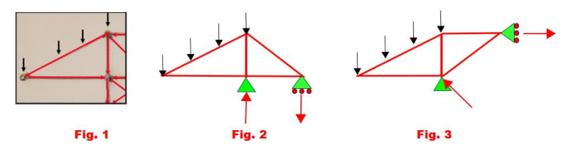
I've drawn an arrow going in both directions but I'm really unsure if its correct, I've been given this by a friend to help solve, the black arrows represent vertical loads and the red arrows the load vectors.

RE: Basic Load paths

if the load is down (inertia load) then the bottom member is in compression and the upper (inclined) member is in tension.

if the load is up (wind load ?) then opposite reactions.

btw, the inclined member needs to resist bending (if it has transverse loads along it's span). But it is still reasonable to assume pinned connections.

"Hoffen wir mal, dass alles gut geht !"
General Paulus, Nov 1942, outside Stalingrad after the launch of Operation Uranus.

RE: Basic Load paths

(OP)
the laods are going down but in this case the load vectors need to show the route a load would take to reach the foundations with the least resistance or aka the shortest path, its essentially impossible to observe but I'm trying to figure out if the best path would be up the diagonal section and down through the vertical sections or down the diagonal sections, across the connected horizontal section and then down the vertical sections.

RE: Basic Load paths

well your picture only shows a tiny portion of the structure, I thought this is what you were interested in.

going into the truss in general it is harder to see the reaction directions. But draw some direction (maybe tension in all members) ... a positive means you had the direction correct, a -ve menas you have compression.

"Hoffen wir mal, dass alles gut geht !"
General Paulus, Nov 1942, outside Stalingrad after the launch of Operation Uranus.

RE: Basic Load paths

There is no "best", "shortest route", or "least resistance" involved in a load path, there is only the flow of the forces through the members based on statics. For the loads on the cantilever there is no single load path. There are forces following multiple paths to multiple supports. Each connection and member along each path must be evaluated for the loads flowing along and through those members and connections.

RE: Basic Load paths

The three figures below indicate similar structures. Fig. 1 does not show the support locations, so it is impossible to know what the truss forces are in all of the members. Figs. 2 and 3 indicate two possible support conditions; red arrows represent reactions.

Boundary conditions must be known before you can solve the problem.

Red Flag This Post

Please let us know here why this post is inappropriate. Reasons such as off-topic, duplicates, flames, illegal, vulgar, or students posting their homework.

Red Flag Submitted

Thank you for helping keep Eng-Tips Forums free from inappropriate posts.
The Eng-Tips staff will check this out and take appropriate action.

Reply To This Thread

Posting in the Eng-Tips forums is a member-only feature.

Click Here to join Eng-Tips and talk with other members! Already a Member? Login


Resources

Low-Volume Rapid Injection Molding With 3D Printed Molds
Learn methods and guidelines for using stereolithography (SLA) 3D printed molds in the injection molding process to lower costs and lead time. Discover how this hybrid manufacturing process enables on-demand mold fabrication to quickly produce small batches of thermoplastic parts. Download Now
Design for Additive Manufacturing (DfAM)
Examine how the principles of DfAM upend many of the long-standing rules around manufacturability - allowing engineers and designers to place a part’s function at the center of their design considerations. Download Now
Taking Control of Engineering Documents
This ebook covers tips for creating and managing workflows, security best practices and protection of intellectual property, Cloud vs. on-premise software solutions, CAD file management, compliance, and more. Download Now

Close Box

Join Eng-Tips® Today!

Join your peers on the Internet's largest technical engineering professional community.
It's easy to join and it's free.

Here's Why Members Love Eng-Tips Forums:

Register now while it's still free!

Already a member? Close this window and log in.

Join Us             Close