×
INTELLIGENT WORK FORUMS
FOR ENGINEERING PROFESSIONALS

Contact US

Log In

Come Join Us!

Are you an
Engineering professional?
Join Eng-Tips Forums!
  • Talk With Other Members
  • Be Notified Of Responses
    To Your Posts
  • Keyword Search
  • One-Click Access To Your
    Favorite Forums
  • Automated Signatures
    On Your Posts
  • Best Of All, It's Free!

*Eng-Tips's functionality depends on members receiving e-mail. By joining you are opting in to receive e-mail.

Posting Guidelines

Promoting, selling, recruiting, coursework and thesis posting is forbidden.

Students Click Here

Uneven Results in Fusion 360 Simulation

Uneven Results in Fusion 360 Simulation

Uneven Results in Fusion 360 Simulation

(OP)
Yo,

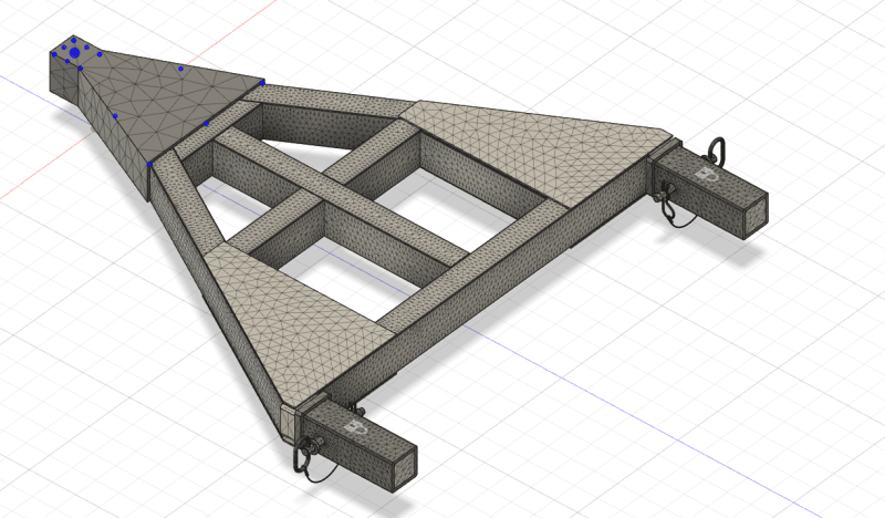
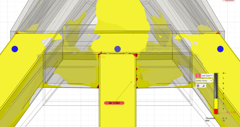
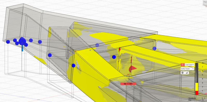
I'm currently running a simulation on a fully symmetric assembly, all other weak spots are symetric on each side except here. The force is acting at the front most point of the assembly and is in the center where the blue dot is. Just trying to figure out why it is so unsymmetrical.


Cheers,
LR

RE: Uneven Results in Fusion 360 Simulation

Post your mesh. What kind of constraints do you have between these elements? Do you have any hand verifications of what you expect to find in these areas?

RE: Uneven Results in Fusion 360 Simulation

(OP)
All parts are bonded and symmetric for contacts since there is no good way to include Weldments. My constraints are located at where the receivers would be attached to the component and are fixed. I don't have hand calculations to show what is expected. But from my knowledge, if you have a symmetric design where force is acting in the midpoint that forces/weak spots would be in the same location as it would be evenly distributed on both sides. If that's not correct, I'd love to know so I can attack this right, this just seems so odd to have one side be this uneven in SF when everywhere else the stresses are equal on both sides.

RE: Uneven Results in Fusion 360 Simulation

If everything in your model is symmetric (including boundary conditions and loads) then you could analyze half of this model and apply symmetry boundary condition to the faces on the plane of the cut.

RE: Uneven Results in Fusion 360 Simulation

(OP)
Awesome, I'll give that a try. Everything is symmetric which is why I am so confused. I appreciate the help!

RE: Uneven Results in Fusion 360 Simulation

Your model, contacts and loads might be symmetric perhaps there is some parts of the mesh that are not symmetric. the FEA model will find even the most minute differences if they are modeled. I think using a symmetric model makes alot of sense and it will save you time.

RE: Uneven Results in Fusion 360 Simulation

In my opinion the likelihood of introducing BC errors is far greater than the time saving. Also, it doesn't really explain the problem does it? Forcing an asymmetric result to be symmetric by mirror imaging is a bodge.

Also welds can be modeled. How on earth do you think fatigue analysis of welded structures is done otherwise?

Cheers

Greg Locock


New here? Try reading these, they might help FAQ731-376: Eng-Tips.com Forum Policies http://eng-tips.com/market.cfm?

RE: Uneven Results in Fusion 360 Simulation

It's not about forcing this behavior, the issue should be resolved anyway. But good practice is to make use of symmetry if possible. Another thing is that those pins should be removed or at least simplified (especially when it comes to the wires hanging from them.

RE: Uneven Results in Fusion 360 Simulation

(OP)
GregLocock, I unfortunately don't have a full version of Fusion at my use... I understand weldments can be implemented but I have no access or don't have the knowledge on how to implement them, hence me stating that there is no good way to include them. If you have an instructional video on how to do that, that'd be great instead of asking how on earth something can be modeled... Sorry for the confusion.

And FEA way, I appreciate the recommendation and the results are more consistent with the IRL failures we are seeing.

Cheers,
LR

RE: Uneven Results in Fusion 360 Simulation

Just an educated guess, but - take a look at the mesh of the triangular plate on the left hand side of the last picture you posted. That mesh does not appear to be symmetric about the obvious line of symmettry. Whether this is because that part is actually not modelled with symmetry, or because the mesher just did it that way, but that kind of mesh variation will create the kind of outputs you are seeing, with the caveat below.

The caveat - you are looking at a plot of "SF", which is kind of an arbitrary, binary yes/no plot. Small, rather insignificant variations in stress can cause the yellow/red "SF" boundary to shift quite a bit. Try looking at the Von Mises stress contours instead, you may see less apparent asymmetry.

Red Flag This Post

Please let us know here why this post is inappropriate. Reasons such as off-topic, duplicates, flames, illegal, vulgar, or students posting their homework.

Red Flag Submitted

Thank you for helping keep Eng-Tips Forums free from inappropriate posts.
The Eng-Tips staff will check this out and take appropriate action.

Reply To This Thread

Posting in the Eng-Tips forums is a member-only feature.

Click Here to join Eng-Tips and talk with other members! Already a Member? Login


Resources

Low-Volume Rapid Injection Molding With 3D Printed Molds
Learn methods and guidelines for using stereolithography (SLA) 3D printed molds in the injection molding process to lower costs and lead time. Discover how this hybrid manufacturing process enables on-demand mold fabrication to quickly produce small batches of thermoplastic parts. Download Now
Design for Additive Manufacturing (DfAM)
Examine how the principles of DfAM upend many of the long-standing rules around manufacturability - allowing engineers and designers to place a part’s function at the center of their design considerations. Download Now
Taking Control of Engineering Documents
This ebook covers tips for creating and managing workflows, security best practices and protection of intellectual property, Cloud vs. on-premise software solutions, CAD file management, compliance, and more. Download Now

Close Box

Join Eng-Tips® Today!

Join your peers on the Internet's largest technical engineering professional community.
It's easy to join and it's free.

Here's Why Members Love Eng-Tips Forums:

Register now while it's still free!

Already a member? Close this window and log in.

Join Us             Close