×
INTELLIGENT WORK FORUMS
FOR ENGINEERING PROFESSIONALS

Contact US

Log In

Come Join Us!

Are you an
Engineering professional?
Join Eng-Tips Forums!
  • Talk With Other Members
  • Be Notified Of Responses
    To Your Posts
  • Keyword Search
  • One-Click Access To Your
    Favorite Forums
  • Automated Signatures
    On Your Posts
  • Best Of All, It's Free!

*Eng-Tips's functionality depends on members receiving e-mail. By joining you are opting in to receive e-mail.

Posting Guidelines

Promoting, selling, recruiting, coursework and thesis posting is forbidden.

Students Click Here

Force distribution along multiple brace bays

Force distribution along multiple brace bays

Force distribution along multiple brace bays

(OP)
I'm designing brace connections but iv been having difficulty understand how to properly distribute the internal loads at the connection node, which is required for the software I use "IDEA StatiCa"
The brace force is 500kN (tension only).
With the geometry I have that gives me a 338.6kN horizontal load that I need to distribute into my beams.
My question is how do I properly distribute that horizontal load into the beams?
What percentage of the 338.6kN goes into my left beam and how much into the right beam?
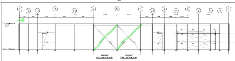
Assuming my wind load is coming from the left as shown below
I'm currently looking at the top brace connection at gridline 5


RE: Force distribution along multiple brace bays

It would be based on stiffness, but in this instance, since they appear to be identical, I would say each brace resists half of the total horizontal load.

However, do they mean 500 kN tension per brace, or total? Because if per brace, which is how I would interpret this drawing, then each of the two roof beams would have the same horizontal component. Or at least that's how I would designit.

RE: Force distribution along multiple brace bays


Assuming the brace force is 500kN (tension only) is for per brace , 338.6kN horizontal compression load for Beam 4-5 , 2X338 kN for beams from gridline 5 to 8 and O.0 kN for beams from grids 1 to 4.. In this case , the horizontal load ( green ) is 2X338 kN.


Tim was so learned that he could name a
horse in nine languages: so ignorant that he bought a cow to ride on.
(BENJAMIN FRANKLIN )

Red Flag This Post

Please let us know here why this post is inappropriate. Reasons such as off-topic, duplicates, flames, illegal, vulgar, or students posting their homework.

Red Flag Submitted

Thank you for helping keep Eng-Tips Forums free from inappropriate posts.
The Eng-Tips staff will check this out and take appropriate action.

Reply To This Thread

Posting in the Eng-Tips forums is a member-only feature.

Click Here to join Eng-Tips and talk with other members! Already a Member? Login


Resources

Low-Volume Rapid Injection Molding With 3D Printed Molds
Learn methods and guidelines for using stereolithography (SLA) 3D printed molds in the injection molding process to lower costs and lead time. Discover how this hybrid manufacturing process enables on-demand mold fabrication to quickly produce small batches of thermoplastic parts. Download Now
Design for Additive Manufacturing (DfAM)
Examine how the principles of DfAM upend many of the long-standing rules around manufacturability - allowing engineers and designers to place a part’s function at the center of their design considerations. Download Now
Taking Control of Engineering Documents
This ebook covers tips for creating and managing workflows, security best practices and protection of intellectual property, Cloud vs. on-premise software solutions, CAD file management, compliance, and more. Download Now

Close Box

Join Eng-Tips® Today!

Join your peers on the Internet's largest technical engineering professional community.
It's easy to join and it's free.

Here's Why Members Love Eng-Tips Forums:

Register now while it's still free!

Already a member? Close this window and log in.

Join Us             Close