×
INTELLIGENT WORK FORUMS
FOR ENGINEERING PROFESSIONALS

Contact US

Log In

Come Join Us!

Are you an
Engineering professional?
Join Eng-Tips Forums!
  • Talk With Other Members
  • Be Notified Of Responses
    To Your Posts
  • Keyword Search
  • One-Click Access To Your
    Favorite Forums
  • Automated Signatures
    On Your Posts
  • Best Of All, It's Free!

*Eng-Tips's functionality depends on members receiving e-mail. By joining you are opting in to receive e-mail.

Posting Guidelines

Promoting, selling, recruiting, coursework and thesis posting is forbidden.

Students Click Here

Continuous Beam w/Cantilever End Spans

Continuous Beam w/Cantilever End Spans

Continuous Beam w/Cantilever End Spans

(OP)
I'm modeling a continuous beam that has 5 spans and the end spans are cantilevers. When all of the spans are equal, the moment at the first supports from the ends from Risa are correct. That is they match the moments calculated using structural analysis; w(l^2)/2.
When the end spans don't equal the interior spans, the negative moment reported by Risa isn't correct. Can anyone tell me why?
Thanks,
Scott

RE: Continuous Beam w/Cantilever End Spans

So, when you go to the Model Settings in RISA (previously known as Global Parameters) there is a setting for Number of Reported Sections and Number of Internal Sections:

The number of reported sections dictates what's reported on the output spreadsheets. The number of internal sections is the approximate number of places where RISA will calculate internal forces, shears, moments, deflections. The number of places along the beam where RISA will do a code check.

In RISA when you have a multi-span physical member you might want to consider one of the following to get more accurate member force diagrams (and code checks!).

a) Increase the number of internal sections.
b) Break the member up into multiple pieces instead of using a single physical member.

RE: Continuous Beam w/Cantilever End Spans

I'm a huge supporter of modeling using Josh's point b)

And it really adds minor additional work during modelling. Still need to have all of the same number of nodes, just a couple extra clicks. At this stage you could break your member at the support node.

Are you modelling the column as well? Is it modelled as fixed or pinned at the connection to the beam?

RE: Continuous Beam w/Cantilever End Spans

- Shear deformations will result in different results than you'll see in the beam tables
- If this is steel I believe RISA has a default setting as part of the direct design to reduce member stiffness as well


Be careful breaking up members most of these software packages will automatically calculate unbraced lengths as the node to node distance, so you'll usually need to manually specify Lb when you break up members with intermediate nodes.

I'm making a thing: www.thestructuraltoolbox.com
(It's no Kootware and it will probably break but it's alive!)

RE: Continuous Beam w/Cantilever End Spans

I am not a RISA user, but surely it should report the correct moment at supports, regardless of the number of subdivisions?

Doug Jenkins
Interactive Design Services
http://newtonexcelbach.wordpress.com/

RE: Continuous Beam w/Cantilever End Spans

Quote (IDS)

I am not a RISA user, but surely it should report the correct moment at supports, regardless of the number of subdivisions?

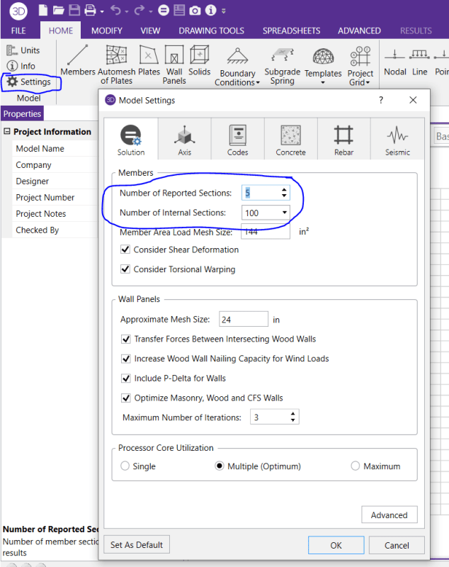
All the calculations and forces are correct. The issue is that the Member results reporting is only done at equally spaced sections (based on those two settings shown in my first post). So, the member force diagrams may miss the support location. Which is why breaking the long member into individual beams for each span is often the best solution.

If Roger and I still worked there, we would have fixed / enhanced this by now wink.... it was something that always bothered us. It just never got a high priority because the large amount of work / re-work that it would have caused without really driving any new sales. Without me and Roger, I suspect there isn't a champion in the office to address this.

Note:
Similar sort of thing for plate stress / force results. If you make a simply supported slab out of plate elements in RISA vs SAP you'll see that the SAP element contours get the contouring correct all the way into the supports..... RISA will shown basically the same contours until you get within a plate or two of the support. There just isn't a boundary correction in contouring for RISA. Not really a big deal and I don't think we got very many user comments about it. But, when I realized SAP was doing a better job than RISA, I wrote up an enhancement ticket with Christine (the smartest PhD developer RISA had) to "enhance" those contours. I actually just found out that Christine isn't there. So, without me or Christine (or a sales motivation) I don't expect this to change.


Caveat:
I worked for RISA for 16 years under the original owner (Bruce Bates). When Bruce sold the company to Numschek, I left under less than cordial circumstances. Now I work for the company that writes SAP2000. So, I have bias here. Especially when it comes to making comparisons between SAP and RISA (as I have done in this post).

RE: Continuous Beam w/Cantilever End Spans

(OP)
Thanks Josh, that did the trick.

Red Flag This Post

Please let us know here why this post is inappropriate. Reasons such as off-topic, duplicates, flames, illegal, vulgar, or students posting their homework.

Red Flag Submitted

Thank you for helping keep Eng-Tips Forums free from inappropriate posts.
The Eng-Tips staff will check this out and take appropriate action.

Reply To This Thread

Posting in the Eng-Tips forums is a member-only feature.

Click Here to join Eng-Tips and talk with other members! Already a Member? Login


Resources

Low-Volume Rapid Injection Molding With 3D Printed Molds
Learn methods and guidelines for using stereolithography (SLA) 3D printed molds in the injection molding process to lower costs and lead time. Discover how this hybrid manufacturing process enables on-demand mold fabrication to quickly produce small batches of thermoplastic parts. Download Now
Design for Additive Manufacturing (DfAM)
Examine how the principles of DfAM upend many of the long-standing rules around manufacturability - allowing engineers and designers to place a part’s function at the center of their design considerations. Download Now
Taking Control of Engineering Documents
This ebook covers tips for creating and managing workflows, security best practices and protection of intellectual property, Cloud vs. on-premise software solutions, CAD file management, compliance, and more. Download Now

Close Box

Join Eng-Tips® Today!

Join your peers on the Internet's largest technical engineering professional community.
It's easy to join and it's free.

Here's Why Members Love Eng-Tips Forums:

Register now while it's still free!

Already a member? Close this window and log in.

Join Us             Close