×
INTELLIGENT WORK FORUMS
FOR ENGINEERING PROFESSIONALS

Contact US

Log In

Come Join Us!

Are you an
Engineering professional?
Join Eng-Tips Forums!
  • Talk With Other Members
  • Be Notified Of Responses
    To Your Posts
  • Keyword Search
  • One-Click Access To Your
    Favorite Forums
  • Automated Signatures
    On Your Posts
  • Best Of All, It's Free!

*Eng-Tips's functionality depends on members receiving e-mail. By joining you are opting in to receive e-mail.

Posting Guidelines

Promoting, selling, recruiting, coursework and thesis posting is forbidden.

Students Click Here

Fastener joint modeling using single RBE2 instead of CBUSH w/ "spider" RBE2

Fastener joint modeling using single RBE2 instead of CBUSH w/ "spider" RBE2

Fastener joint modeling using single RBE2 instead of CBUSH w/ "spider" RBE2

(OP)
Hello,

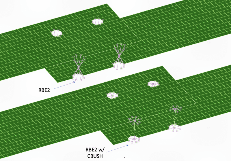
I have a question I was hoping you all could answer. A coworker sent me an FE model that he created, where he modeled a bolted joint using just an RBE2 element (with DOFs in 123) to connect the matching holes in 2 plates. I would never do this; my preferred modeling method would be to add a CBUSH element between the two holes and then connect each end to their respective plate with an RBE2.

Is it even possible to extract usable MPC forces from my coworker's model? When I plot the MPC forces marker, I get 0 lbf in every direction. Is this due to the summation of forces at the independent node or something? I know that RBE2s are infinitely stiff, so I suspect any forces/stresses at this type of joint wouldn't even be realistic or worth assessing.

I've attached a picture of a quick FEA mockup of a joint with just an RBE2 vs my preferred method of a CBUSH w/ RBE2s.


Thanks for the input!

RE: Fastener joint modeling using single RBE2 instead of CBUSH w/ "spider" RBE2

Ugh, both methods are awful (his more so). Sigh. Why do people insist on modelling the holes then stick an infinitely stiff element in the “hole”? (Yeah, I get it, its easy to blindly automesh using the CAD model).

RE: Fastener joint modeling using single RBE2 instead of CBUSH w/ "spider" RBE2

How would you model a joint SWComposites?

RE: Fastener joint modeling using single RBE2 instead of CBUSH w/ "spider" RBE2

I would not model the holes in the plates. For a two strap joint, I would connect a node in each plate (strap) with a CBUSH (if Nastran) or a fastener element (if Abaqus). For a three or more strap joint, a Ruttman type modelling method is needed to ensure fastener continuity.

RE: Fastener joint modeling using single RBE2 instead of CBUSH w/ "spider" RBE2

I agree ... but sort dismissed by the OP, no?

"Hoffen wir mal, dass alles gut geht !"
General Paulus, Nov 1942, outside Stalingrad after the launch of Operation Uranus.

RE: Fastener joint modeling using single RBE2 instead of CBUSH w/ "spider" RBE2

SWComposites, so for Nastran do you remove the hole in the surface adding a node at the center, then connect those via a CBUSH?

RE: Fastener joint modeling using single RBE2 instead of CBUSH w/ "spider" RBE2

Essentially, yes. Remove the holes in the CAD model or surface before meshing. Then figure out how to force the mesh to have nodes at the fasteners. Or use a code with meshless fastener elements.

RE: Fastener joint modeling using single RBE2 instead of CBUSH w/ "spider" RBE2

if you have holes (like in a 3D mesh CAD part), retain the center point/vector and delete the hoe.

if you are doing a 2D model, mesh as you like and use element results (shear/in) to derive fastener loads.

obviously use more attention for discrete high load fasteners (wing attach) than "ordinary" skin/frame of skin/stringer rivets.

"Hoffen wir mal, dass alles gut geht !"
General Paulus, Nov 1942, outside Stalingrad after the launch of Operation Uranus.

RE: Fastener joint modeling using single RBE2 instead of CBUSH w/ "spider" RBE2

rb - LOL, "use element results (shear/in) to derive fastener loads" is a nearly lost art. It seems these days that if the FEM postprocessor doesn't auto plot a (often rubbish) result, then analysts have no clue how to determine it. I can't count the times I almost lost my mind when I asked for a (balanced) free body diagram and got a nearly unintelligible Patran image generated by the internal FBD generator. Sigh.

RE: Fastener joint modeling using single RBE2 instead of CBUSH w/ "spider" RBE2

ditto ... sigh

"Hoffen wir mal, dass alles gut geht !"
General Paulus, Nov 1942, outside Stalingrad after the launch of Operation Uranus.

RE: Fastener joint modeling using single RBE2 instead of CBUSH w/ "spider" RBE2

I'm not trying to take over this thread but @rb1957 can you elaborate on "use element results (shear/in) to derive fastener loads."

RE: Fastener joint modeling using single RBE2 instead of CBUSH w/ "spider" RBE2

you can get shear flow from the FEM. sometimes directly from the elements, sometimes with some manipulation.

eg a skin splice between two elements may be directly Fxy, from FE output.
shear flow into a frame cap (or shear splice) may require some additional element addition/subtraction.

then what is the typical rivet spacing

and so the typical rivet load = (load/in)/(rivets/in)

"Hoffen wir mal, dass alles gut geht !"
General Paulus, Nov 1942, outside Stalingrad after the launch of Operation Uranus.

Red Flag This Post

Please let us know here why this post is inappropriate. Reasons such as off-topic, duplicates, flames, illegal, vulgar, or students posting their homework.

Red Flag Submitted

Thank you for helping keep Eng-Tips Forums free from inappropriate posts.
The Eng-Tips staff will check this out and take appropriate action.

Reply To This Thread

Posting in the Eng-Tips forums is a member-only feature.

Click Here to join Eng-Tips and talk with other members! Already a Member? Login


Resources

Low-Volume Rapid Injection Molding With 3D Printed Molds
Learn methods and guidelines for using stereolithography (SLA) 3D printed molds in the injection molding process to lower costs and lead time. Discover how this hybrid manufacturing process enables on-demand mold fabrication to quickly produce small batches of thermoplastic parts. Download Now
Design for Additive Manufacturing (DfAM)
Examine how the principles of DfAM upend many of the long-standing rules around manufacturability - allowing engineers and designers to place a part’s function at the center of their design considerations. Download Now
Taking Control of Engineering Documents
This ebook covers tips for creating and managing workflows, security best practices and protection of intellectual property, Cloud vs. on-premise software solutions, CAD file management, compliance, and more. Download Now

Close Box

Join Eng-Tips® Today!

Join your peers on the Internet's largest technical engineering professional community.
It's easy to join and it's free.

Here's Why Members Love Eng-Tips Forums:

Register now while it's still free!

Already a member? Close this window and log in.

Join Us             Close