×
INTELLIGENT WORK FORUMS
FOR ENGINEERING PROFESSIONALS

Log In

Come Join Us!

Are you an
Engineering professional?
Join Eng-Tips Forums!
  • Talk With Other Members
  • Be Notified Of Responses
    To Your Posts
  • Keyword Search
  • One-Click Access To Your
    Favorite Forums
  • Automated Signatures
    On Your Posts
  • Best Of All, It's Free!

*Eng-Tips's functionality depends on members receiving e-mail. By joining you are opting in to receive e-mail.

Posting Guidelines

Promoting, selling, recruiting, coursework and thesis posting is forbidden.

Students Click Here

Interesting tire slip question

Interesting tire slip question

Interesting tire slip question

(OP)
Greetings,

Interesting question: if we have a solid axle of a vehicle traveling in a straight line path, do the two tire velocity vectors always need to be parallel, i.e., do the tires have to have the same slip angle? (I'm imagining a vehicle traveling along a banked section of pavement, for instance, where the loading on the wheels won't be equal.)

Thanks in advance.
Replies continue below

Recommended for you

RE: Interesting tire slip question

(OP)
Thank you, Greg.

Then extending the question just a bit, if we have this straight-traveling solid axle where I will presume that all compliance resides only in the tires, then for a hypothetical car traveling along a flat surface banked left or right, and with a positive COG height, then with the lower tire having greater loading then the higher one, this lower tire will experience larger slip than the higher one. And if so, then the tires are toed-out according to their differing velocity vector orientations. Correct? (I'd rather bypass camber until I get past this simpler question.)

RE: Interesting tire slip question

Start with a skateboard car, no kinematics or compliances. The forward velocity at the outer tire patch is greater, due to R, the lateral velocity is the same for each, steady state. For the tire if there are no toe effects and no yaw then the slipangle of the outer tire (atan(vy/vx))is less than that of the inner.

Cheers

Greg Locock


New here? Try reading these, they might help FAQ731-376: Eng-Tips.com Forum Policies http://eng-tips.com/market.cfm?

RE: Interesting tire slip question

(OP)


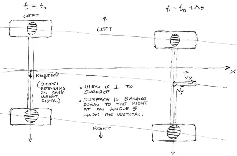
Thanks again. I think you're saying we get toe-in rather than toe-out. To make sure I communicated my second question clearly, please look at the diagram above. (For the time being, I'm only suggesting tire velocity vectors.) Was this your understanding as well? Vx and Vy are for the entire axle and not the tires, incidentally. Also, assume neutral steer so the path has no curvature.

RE: Interesting tire slip question

(OP)
Drats, I just wrote a long edit to that last post and it got lost...

Perhaps I should have said "inclined" instead of "banked." Again, assume the pavement is flat and has no curvature. R is infinite, if you will.

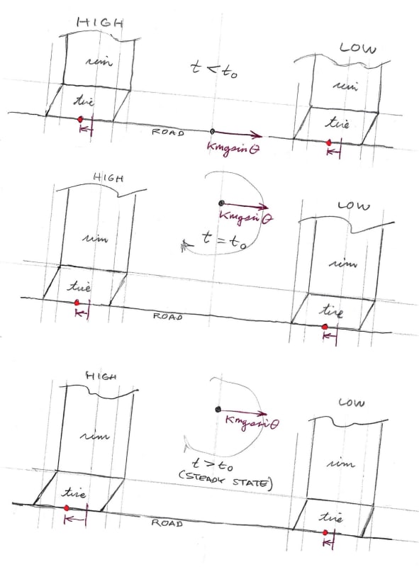
Also, I believe the velocity vectors do initially diverge due to unequal tire loading and the COG height. So the initial slips are unequal. The slips cause the contact patches to drift away from each other, deforming the tires. This deformation creates a restoring force on each patch. Collectively, the restoring forces are equal, opposite, and internal to the system. The deformation grows until equilibrium is reached. In this equilibrated state, the tires acquire something somewhat akin to negative camber*, the velocity vectors restore to parallelism, and the slips become equal.

I'm guessing the transition from unequal to equal slips may occur very quickly, maybe something like a quarter of a tire rotation for a 5-degree-ish pavement inclination.

How does this sound? Thx.

(*This is in addition to the tire deformation created by the external k*mgsin(theta) force.)

RE: Interesting tire slip question

(OP)
My conclusion too, in the steady state. Thx.

RE: Interesting tire slip question

Your solid axle is a rigid body. The inside and outside tires will have different Fz loads on them, and this results in different Fy, Mx, and Mz outputs from the tires. Probably different camber angles, too because of deflection steer, plus roll steer and roll camber. But, the rear axle's slip angle, will have the same slip angle (velocity based as you stated). Of course the transition to get to a common BODY slip angle involves some transient Fy, Mx, and Mz force & moment iteration involving individual rear tire steer & camber angles.

RE: Interesting tire slip question

(OP)
Thanks, Cibachrome. I'm curious about the description of the transient to the steady-state transition where the steady state would have the tire contact patches spread a bit farther part from each other than would be the case if the tire normal loadings were equal. Is this valid?

RE: Interesting tire slip question

It all gets balanced out, taking into account tire reactions, symmetric & asymmetric mechanical and geometrical compliances, shock forces, (they're usually asymmetric because of jounce & rebound tunings), and induced sprung mass roll consequences. In a proper and inclusive simulation in yaw velocity, side-slip, and roll State Variables, all this gets to play out. Very important in all of this vehicle dynamics are the tire relaxation mechanisms. Load, slip/steer, and speed dependent, they modulate all this interaction. Mz relaxation is quite a power player in this because of high initial steering moment buildup and it's phasing with Fy. Again, all this gets to play out in a parametric simulation.

RE: Interesting tire slip question

As for spreading out contact patches, each tire's Mx moment (overturning moment) moves this around in addition to slip induced Fy. Yes camber is in there, too. What's interesting about Mx is that it can change sign at some slip angle as you load it up. This here ain't such a good thang because at or near incipient roll-over, you're gunna break some glass when this happens. Racers call it snap-thru.

Also, in the exact same size, rim width, pressure and load, different brands can (and do) exhibit different signs and magnitudes of Mx. Even for the same Fy and Mz characteristics.

So there's no yes or no answer. Having all the data from a K&C test plus some tire information hands you the answer for each tire. They're probably not nearly the same going straight ahead for all the same reasons: weight, rotation direction, power/differential asymmetry, road crown.

RE: Interesting tire slip question

(OP)
Hmmm. Interesting and thank you once again, cibachrome. I think to make significant headway here we'd all need to be standing in front of a whiteboard. Trying to do this with words is very cumbersome...

RE: Interesting tire slip question

It would help if you would separate tire slip angle and tire lateral velocity terms. They are not the same. The whole axle and its components are all at the same lateral velocity otherwise they would both go their separate ways. Tire slip angles on the other hand can be different because angle is not the constraint, Net force AND the Mz Mx moments do a dance to balance themselves by axle and by vehicle velocities.

Just think of the front axle of a car. Big, wide high cornering stiffness and high grip tire on the left front position. On the right front, the tire is bigger, wider, with LOWER stiffnesses and grip level.
So you steer to the left (usually all the time, btw), The left tire calls the shots and carries the cornering burden. The right side tire and be at 30 degrees toe (Oops, hit the wall). the right side tire is smoking but the car goes pretty much where the left side tire wants to go. And at just a bit higher slip angle than normal.

RE: Interesting tire slip question

(OP)
Hi Cibachrome - All of that makes sense. My hypothetical axle is in static equilibrium after the steady state is attained, so the external moments and forces must sum to zero. The initiation of the transient state as I've described it could be created by having the vehicle's COM height go from zero to whatever might be its nominal value for t > t naught.

Some assumptions about this axle: No differential. No roll steer. No assumptions whatsoever about its suspension aside from ensuring the conditions shown in my sketch are met. Identical tires left and right. So, this axle doesn't exist in real life, just as massless rods with infinite rigidity, which are cited everywhere in physics discourses, don't exist either. Even so, I think considering what happens to this axle has valid real-world implications.

Here's my understanding of what's going on here:

We know for t> t naught that the forces and the moments change. The lower tire becomes more heavily loaded than the higher one. The lateral force from the lower tire is greater than from the higher tire. Without considering pneumatic trail for the time being, the slip angle for the lower tire *must* be (please correct me if I'm wrong) greater than for the higher tire.

We know this divergence in slip (and therefore tire contact patch velocities) can't continue indefinitely, or the axle will separate, or the higher tire will start to slide.

So at some time after t = t naught, static equilibrium is attained, the tire velocities restore to parallelism (probably exponentially over time), and the slip angles become equal. Regarding pneumatic trails, we assign to our imaginary suspension the additional task of creating an equal and opposite Mz to maintain zero yaw acceleration.

So in summary, the tire slip angles go from initial divergence (toe-out) in the transient state to parallelism (zero toe) in the steady state. Looking at Fy for each tire contact patch, the equalizing factor arises from tire deformation. It's simply an inevitable consequence of the differing tire velocities. As the initial paths diverge and the tire deformations grow, the deformations create equal and opposite internal forces (for the axle, that is,) that likewise grow, until the sum of the internal and external forces acting on each contact patch equalizes. When this sum equalizes, the slip angles become the same for both tires and the pneumatic trails become equal.

So there are three things influencing tire shape happening here. The first is the axle overturning Mx moment as you call it, which somewhat compresses the lower tire's sidewall and slightly extends the higher tire's sidewall. Then we have the kmgsin(theta) force exerted on the axle arising from the rear axle's burden of the vehicle's weight, creating negative camber for the higher tire and positive camber for the lower tire. And then finally we have this changing camber in the transient state arising from the divergent velocities causing the contact patches to spread a bit farther apart from each other. This camber contribution is negative for both tires.

On edit, here's a schematic sketch of what I believe is happening as time passes:


I hope I'm not needlessly repeating myself but hopefully, this clarifies my thought process; please feel free to shoot this theory full of holes as needed. That's why I came here!

RE: Interesting tire slip question

One more (and the last) time: Your axle does not function from forces generated by slip angles. The non-steered tires are PLUNGED, so the slip angles RESULT from the summation of Forces and MOMENTS generated by yawing and sides-slipping on both wheels, induced by gravity or the other, steered axle. Your axle (as you defined it, is a rigid body. The overall problem you face is how the vehicle settles up (or down) during any transient portion to get a common slip angle to obtain a steady state force and moment balance. Any decent simulation will show you this. Make sure you include all the moments, too. That's the 'difficult' situation to solve for and one reason simulationistas ignore them. You stated no compliance, no roll steer or camber and equal tires with equal cornering stiffnesses, no conicity, ply-steer, or residual aligning moment properties.

Your diagram ought to show (unequal) force & moment vectors instead.

RE: Interesting tire slip question

(OP)
OK. I agree about additionally showing forces and moments, but I think the resulting visual would have been much too dense. I'm far outside of this field and have no access to simulations nor sufficient curiosity to pay for the pertinent seat license(s) to achieve simulations.

About the slip and lateral force, and the chicken-first or the egg-first question, I also come down on the side of the lateral force being the cause and the slip being the effect, although Milliken seems to do it the other way around. If you read my last post carefully, you'll see that that was how I was describing it. Functionally, the two approaches are identical so I won't sweat the distinction.

So, I'll leave it at that unless anyone else has anything to add. Cibachrome, many thanks for your explanations and your patience.

Red Flag This Post

Please let us know here why this post is inappropriate. Reasons such as off-topic, duplicates, flames, illegal, vulgar, or students posting their homework.

Red Flag Submitted

Thank you for helping keep Eng-Tips Forums free from inappropriate posts.
The Eng-Tips staff will check this out and take appropriate action.

Reply To This Thread

Posting in the Eng-Tips forums is a member-only feature.

Click Here to join Eng-Tips and talk with other members! Already a Member? Login


News


Close Box

Join Eng-Tips® Today!

Join your peers on the Internet's largest technical engineering professional community.
It's easy to join and it's free.

Here's Why Members Love Eng-Tips Forums:

Register now while it's still free!

Already a member? Close this window and log in.

Join Us             Close