DC motor fault and consequences
(OP)
Good morning all,
My bias is towards control systems so when I was met with a DC motor fault yesterday I have had to admit where the shortcomings in my knowledge are and clearly it is DC motors.
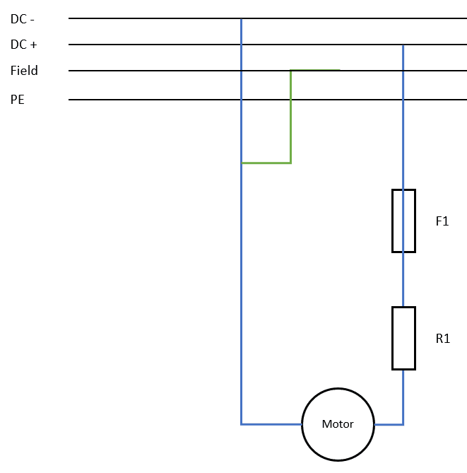
I have the circuit below (simplified for clarity):
The incident that occurred (as far as I can make out) is that during running of this motor the resistor bank got extremely hot and caused some thermal damage to it's casing. What I'm trying to understand is why this has happened.
It appears that the field wiring became disconnected. Now from the research that I have done this would seem to then cause a huge spike in the armature current (which explains the thermal damage) but what I don't understand is why the fuse did not trip? Also can someone please explain to me why this causes a spike in the armature current?
Final question is can anyone recommend anywhere that I can do some training/reading up on DC motors and their control/operation?
Thanks!
Tom
RE: DC motor fault and consequences
1) Armature winding. Very few turns (usually only 1 and sometimes 2), therefore relatively large current. Current flow through the winding magnetizes the rotating core. Requires switching (i.e., commutation) of some sort to continually switch magnetic field polarity as it rotates.
2) Main field winding. Lots of turns and relatively low current. Usually fed from separate controllable current source to allow magnetic field strength adjustment (and therefore speed adjustment). Due to separate source, usually has constant magnetic field polarity.
3) Commutating pole (interpole) winding. Usually conductor has large cross-section and few turns as it carries armature current. Used to force a change in the voltage in armature, driving toward zero to allow minimum disruption at "switching" point. Located on more slender pole bodies between the "main" poles.
4) Compensating pole (pole face) winding. Large conductor, few turns, carries armature current. Adjusts "focal" point of main field as load changes to try and keep strongest field at pole centerline for maximum effectiveness. (Distortion of field caused by rotation of armature - think about pulling a rubber band to the side, instead of straight vertically.) Found on larger machines where there is room for it - it is located in the pole "shoe" of the main pole, close to the air gap.
5) Stabilizing field winding. Can be large turn count / low current OR low turn count/high current. In either case, it is fed in parallel with the armature (current divided based on relative circuit resistance). Intent is to be cumulative (additive) to the main field strength OR to be differential (subtractive) to the main field strength. Found on older designs, particularly with wide speed ranges.
Now to how it operates.
A) Voltage is applied to the (low resistance) armature circuit, causing large amounts of current to flow. In your case, you have an additional external resistor (R1) in series to limit this to some value that the winding itself cannot. If R1 gets hotter, its apparent resistance gets larger and the current through the armature is reduced. If R1 "short circuits", it effectively has zero resistance and the armature current is no longer restricted by anything but its own resistance - so it increases (probably dramatically and virtually instantaneously).
B) The field winding controls the speed of rotation: more current equals more magnetic field strength equals lower speed. (Hint - we're back to the rubber band analogy.) Loss of field (i.e. no current in the field circuit) is a condition that causes two things to occur. The first is that the armature will try to accelerate virtually instantaneously to some astronomical point - how far it gets and how fast it gets there is related to the inertia of the connected load. The second thing that happens is that the armature also sees an effective short circuit condition (for a very short period of time, at least) which translates into a probable flashover at the brush-commutator interface. The reason the armature current increases is that with the loss of field strength in the pole, the armature voltage has no "deterrent" (back EMF), so the full effect of the applied voltage causes current to increase. Remember that the armature has very few turns - which means virtually no inductance. The lack of inductance means that current can change VERY rapidly (on the order of 0.1 to 0.2 microsecond for a 1 per unit step change).
What is a flashover? It's where an electrical arc develops (and sustains itself) between brushes (and/or holders) of opposite polarity, or between one brush/holder polarity and ground. Regardless which it is, the armature circuit now effectively looks like a "short" to any controller - which means the appropriate fault sequence kicks in. Usually, the response is to turn off the armature voltage first since that knocks the major source off the circuit. However, the rotational motion is not likely going to stop immediately which means the armature winding is still turning within an energized magnetic field created by the main poles. Turning off the main field supply will drop that field strength to the residual magnetism level, which will greatly reduce the damage associated with the event.
Converting energy to motion for more than half a century
RE: DC motor fault and consequences
I have a couple of further questions that this has raised:
1. So it is looking like the lack of a field current has meant that there is no longer any back EMF. If the current was to raise that rapidly and to that sort of an order of magnitude then why didn't the fuse blow? The only explanation that I have is that the resistance of R1 kept the armiture current below the point at which point the fuse would have blown?
2. Are you reliant on a system within the drive to detect the loss of a field current or would there be a way to put overcurrent protection in to prevent a fire if we were to lose the field again?
Thanks again!
RE: DC motor fault and consequences
hi:waving:
am new in the forum
I have a problem with a dc drive
let me start with the application
it's a centrifugal force pump that runs with a dc motor without a gearbox, the operation speed is 1300 rpm working 24/7
the problem is the speed drops from 1300 rpm to 200 rpm instantaneous and back to 1300 rpm without any user interference. happens at random times like 5 times / h and could be 1 time /day but happens every day
we made some solutions but the problem is still on ( until step 5 )
1- change speed reference pot ( 10k ohm, 5k ohm all 10 turns )
2-change start stop push buttons, control relays, power, and control cables from panel to motor and from panel to operator panel
3-change speed reference from pot to push button ( option in the drive )
4-change motor :38:
5-last changed the control card on the drive
but this made the 1st problem gone and a new one appear
the drive stop without any fault as if someone pressed the stop push button so we change it but the problem still on
can someone help
RE: DC motor fault and consequences
1) The fuse is designed to "fail safe" (i.e., become open circuit) when the current reaches a specific amplitude for some defined duration. This begs the following investigation: A) what amplitude triggers the fuse used? B) How long does it have to be maintained at - or above - the "trip" level? C) Once the point is reached, how long does it take the fuse to actually "open"? The reason these need to be asked is because your DC source is - most likely in today's environment - a drive. The drive has internal sensors looking at currents and voltages (at input, output, and various internal choke points) to protect itself (and hopefully the rotating machine connected to it) from potentially harmful conditions such as over-voltage and over-current. It is also looking at them to try and protect personnel from injury caused by thermal, electrical, or mechanical failures in the rotating equipment. So the question becomes - which happens faster: the fuse or the drive's own sensing? Either one can "turn off" the armature current.
2) Modern DC drives definitely have some sort of logic circuit that is looking at "loss of field" condition. The biggest problem is that the cheaper drives tend to only look at what is passing through the drive itself - as a result, they cannot always tell if the conductor between the drive terminal and the winding (or even the winding itself) has become open-circuit. As iop95 mentioned, it is often possible to add additional "external to the drive" sensors that feed back into the logic to determine parameters associated with the actual condition of the rotating machine. All it requires is a device to be installed to measure the critical data, enough I/O points to bring the signal into the drive, and tweaking of the control logic to use the information correctly (and effectively).
Converting energy to motion for more than half a century
RE: DC motor fault and consequences
So we now must ask a couple of key questions about the application: A) what fluid is being pumped? B) how much brake horsepower is required to operate the pump at the desired pressure/flow point? C) what is the DC machine rated for in terms of power at the desired speed point - in particular, is the operating speed at or below the "base" speed of the machine, or is it in the field weakened range (somewhere between "base" and "top" speed)?
The reason(s) why the machine might drop from 1300 to 200 rpm can include:
1) Loss of main field current (see tommatwalker's posts above, with my previous responses) causing loss of torque - and consequent reduction in impeller speed.
2) Sudden increase in load torque demand (a frozen chunk of normally-malleable slurry, for example) exceeds ability of drive to provide power (i.e., current) causing the process to reduce speed to where it can maintain the output current safely.
3) Something causes a loss-of-signal in one of the feedback loops, so the drive no longer knows what is going on. In most cases, the default programming of a drive is to return the equipment to a "safe" state - however that is defined - until the situation regarding the signal is resolved. A reduction in torque output (and therefore speed) is the most common approach.
4) The controller itself (the basic logic card) has a fault which precludes correct operation.
Converting energy to motion for more than half a century