Hello all,
I have a trouble assessing the FEA results of a set-in nozzle on a dished end.
Design pressure of a vessel p = 40 atu = 40,53 bar; temperature T = 100°C.
Due to changed pipe routing the existing vessel's nozzle should be checked against the loads from piping, but high stresses due to internal pressure lead me to further questions.
Analysis is done with ROHR2fesu module according to EN 13445-3 standard.
The method is based on 2D shell elements.
I do not understand how exactly the junction of a nozzle with a shell is defined in the FE model.
In my specific case/example, I have a nozzle/jacket according to Figure 1.
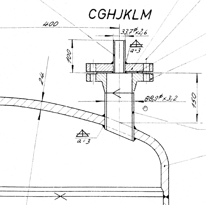
Figure 1
Question
From the cross section (Figure 2) it can be seen that the junction is made in the median point of a shell wall. That is why defined pressure of element No. 4998 is 0 bar(g). However, the nozzle element above, which is still located in the shell wall have pressure 40 bar(g).
Is this a wrong simplification and can the calculation be verified this way? What about welds on both sides of the jacket and the elements that are still located in the shell wall?
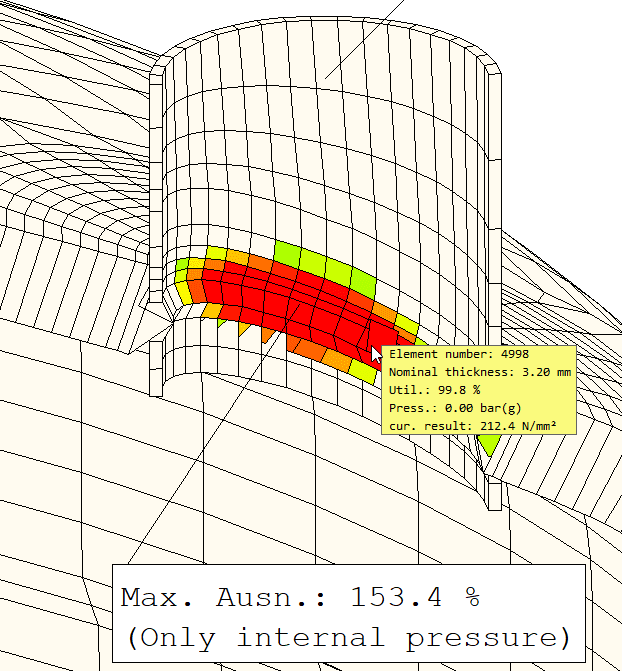
If I consider only internal pressure the nozzle is already overloaded, even if I classify these elements as local.
I am thinking about ignoring internal pressure loads for the area of the nozzle located in the dished end wall. Would this be the correct apporach?
Thank you in advance!
I have a trouble assessing the FEA results of a set-in nozzle on a dished end.
Design pressure of a vessel p = 40 atu = 40,53 bar; temperature T = 100°C.
Due to changed pipe routing the existing vessel's nozzle should be checked against the loads from piping, but high stresses due to internal pressure lead me to further questions.
Analysis is done with ROHR2fesu module according to EN 13445-3 standard.
The method is based on 2D shell elements.
I do not understand how exactly the junction of a nozzle with a shell is defined in the FE model.
In my specific case/example, I have a nozzle/jacket according to Figure 1.
Figure 1
Question
From the cross section (Figure 2) it can be seen that the junction is made in the median point of a shell wall. That is why defined pressure of element No. 4998 is 0 bar(g). However, the nozzle element above, which is still located in the shell wall have pressure 40 bar(g).
Is this a wrong simplification and can the calculation be verified this way? What about welds on both sides of the jacket and the elements that are still located in the shell wall?
If I consider only internal pressure the nozzle is already overloaded, even if I classify these elements as local.
I am thinking about ignoring internal pressure loads for the area of the nozzle located in the dished end wall. Would this be the correct apporach?
Thank you in advance!