Howdy all,
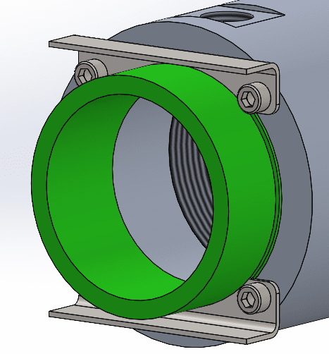
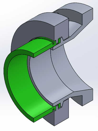
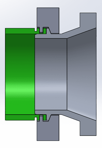
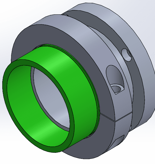
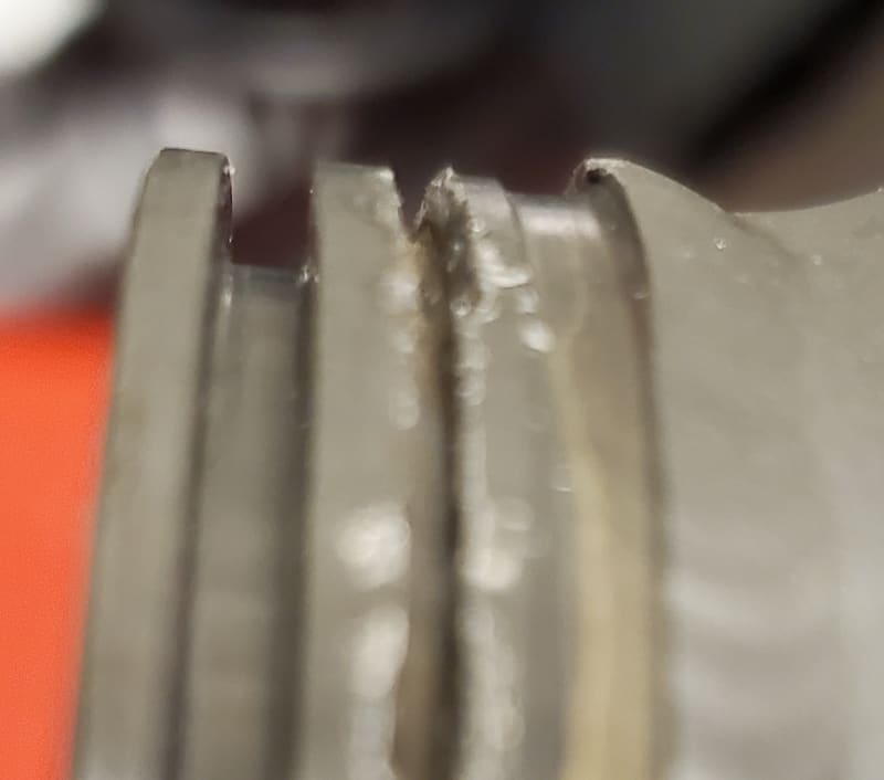
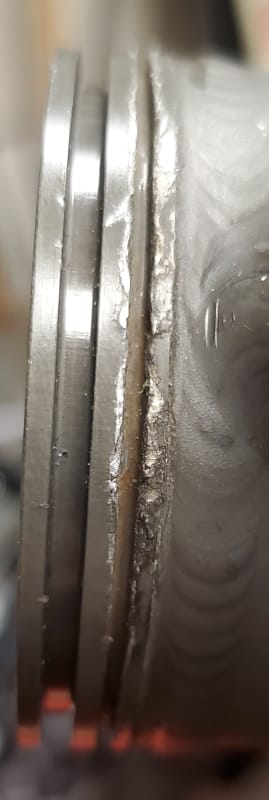
I'm designing the tooling to test a pneumatic motor and I'm stumped by this connection in the pictures below. It's a 2.25" OD with two grooves. The first grove, the larger one I thought was an O-ring gland, but it's a bit narrow at .091 inch and way too deep at .125 inch. The second, smaller groove is just .050 inch wide and .080 inch deep. I designed a connection that "works" using a couple stacked O-rings (size 033) and uses the narrow slot to fit some machined L-angles with bolts to hold the attachment sleeve in place. I'm just not happy with my design and I might make a better connector if I knew how this connector is supposed to work. This is for the pneumatic actuator motor on a 747 leading edge flap drive.
Anyone familiar with the mating connector that matches this port?
Thanks,
-Kirby
Kirby Wilkerson
Remember, first define the problem, then solve it.