×
INTELLIGENT WORK FORUMS
FOR ENGINEERING PROFESSIONALS

Contact US

Log In

Come Join Us!

Are you an
Engineering professional?
Join Eng-Tips Forums!
  • Talk With Other Members
  • Be Notified Of Responses
    To Your Posts
  • Keyword Search
  • One-Click Access To Your
    Favorite Forums
  • Automated Signatures
    On Your Posts
  • Best Of All, It's Free!

*Eng-Tips's functionality depends on members receiving e-mail. By joining you are opting in to receive e-mail.

Posting Guidelines

Promoting, selling, recruiting, coursework and thesis posting is forbidden.

Students Click Here

CT circuit

CT circuit

CT circuit

(OP)
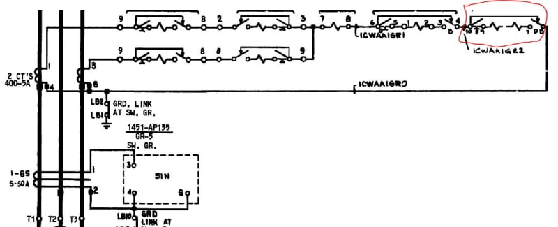
We have 2 CTs (A and C phase) on the 3-ph motor circuit and the CTs are wired as follows:
1) 2 CTs feed motor protection relays followed by the summated CT (2 CT currents summed before) feeding the motor excitation panel.

We are replacing the motor excitation panel that now requires 2 separate CT inputs. So we have been planning to revise the CT circuit as follows:
2a) 2 CTs feed motor excitation panel (add 1200 ft round trip) followed by the motor protection relays
2b) Alternatively, the 2 CTs can feed the motor protection relays first followed by the motor excitation panel (placement of the panel is reverse of option 2a)

Preliminary calculation shows that the increased CT burden is acceptable. What would be your recommendation 2a or 2b? For option 2a, would this have any negative impact to motor protection?

Thanks for your input.

RE: CT circuit

I would choose 2b, just because.

RE: CT circuit

I think Electricpete should answer this one.

RE: CT circuit

Where are the CTs located - in the switchgear panel I suppose!
Is there no third CT (in Y-phase)? How is earth fault protection ensured if there is no third CT - Is there Zero sequence (Core Balance) CT in the panel?
Motor protection relay is in switchgear panel and the Excitation panel is near motor I guess.
1) If there is ZSCT, both options (2a & 2b) mentioned by you are possible and either has no specific advantage.
2) If you don't have a ZS CT but have third CT then, I would prefer option-2a.

RE: CT circuit

(OP)
Thanks Raghunath, steve and cranky108.

1) Yes, CTs are located in the 4kV switchgear panel.
2) Yes, excitation panel is near the motor (600 ft away from the swgr; hence 1200 ft of additional CT wiring)
3) No 3rd CT or zero sequence CT.

Hope this clarifies.

RE: CT circuit

(OP)
I forgot to add. Also, @Raghunath, can you please provide the reasoning behind why 2a or 2b?

RE: CT circuit

SaraXelon,
You said there is no CT in Y-phase and also no ZS CT.
In such a case, I expected you to explain how is the installation protected against single phase to ground faults?

RE: CT circuit

(OP)
Sorry for the delay.

I went through the drawings, there is a separate CT on A phase for 51N relay. This CT is completely different from the excitation panel CTs on A and C phase.

RE: CT circuit

SaraXelon,
"there is a separate CT on A phase for 51N relay" - I think you are wrong here.
You may like to check again.

RE: CT circuit

I've seen many examples over the years of a high-impedance grounded system having had CTs on A and C, EM relays connected to those CTs and a separate CBCT (core balance aka zero sequence) around the three phases. Any single phase fault would only show up of the neutral/ground relay connected to the CBCT. Any other fault would involve at least one of A or C. When the EM relays were to be replaced, but the owner was too cheap to add the B-phase CT, the thing to do was to run A and C to the relay, then sum them and run that backward through the B-phase connection. B = -(A + C) for any reasonably balanced system. With the high impedance grounded system that worked. Then the CBCT circuit needed to be run through the single phase current inputs of the relay (either ground or neutral depending on the manufacturer's naming convention).

I’ll see your silver lining and raise you two black clouds. - Protection Operations

RE: CT circuit

(OP)
Raghunath,

Nothing to check. See picture below. Highlighted is the excitation panel that we would like to move before the summation point - either before the protection circuit or after the protection circuit like I explained in my OP

RE: CT circuit

SaraXelon,
The CT connected to 51N is CBCT (also called ZS CT).

RE: CT circuit

Depending on which way it goes into the device, that current is either B or -B. If you connect to either A or C before the summing point that's what you'll have, A or C (or -A or -C depending). One motor by itself and it probably doesn't matter which phase it's on.

I’ll see your silver lining and raise you two black clouds. - Protection Operations

RE: CT circuit

(OP)
Thanks for all responses. But the original question still remain. Where to connect the excitation panel, before the motor protection (nearest point is CT) or after the motor protection protection (just before the CT summation point) in the 2 CT (A and C) circuit?

RE: CT circuit

As long as it's after the summation point, current is current, doesn't matter.

I’ll see your silver lining and raise you two black clouds. - Protection Operations

RE: CT circuit

(OP)
But the new excitation panel requires 2 separate CTs. That's why my original post. In the 2 CT configuration, where to connect the excitation panel, before the motor protection (nearest point is CT) or after the motor protection protection (just before the CT summation point)?

Also, what would be the reasoning (if I have to explain someone it helps)

RE: CT circuit

You probably have to put the excitation panel first with the CTs more or less just passing through it and then do the summing at the protection relay.

Red Flag This Post

Please let us know here why this post is inappropriate. Reasons such as off-topic, duplicates, flames, illegal, vulgar, or students posting their homework.

Red Flag Submitted

Thank you for helping keep Eng-Tips Forums free from inappropriate posts.
The Eng-Tips staff will check this out and take appropriate action.

Reply To This Thread

Posting in the Eng-Tips forums is a member-only feature.

Click Here to join Eng-Tips and talk with other members! Already a Member? Login


Resources

Low-Volume Rapid Injection Molding With 3D Printed Molds
Learn methods and guidelines for using stereolithography (SLA) 3D printed molds in the injection molding process to lower costs and lead time. Discover how this hybrid manufacturing process enables on-demand mold fabrication to quickly produce small batches of thermoplastic parts. Download Now
Design for Additive Manufacturing (DfAM)
Examine how the principles of DfAM upend many of the long-standing rules around manufacturability - allowing engineers and designers to place a part’s function at the center of their design considerations. Download Now
Taking Control of Engineering Documents
This ebook covers tips for creating and managing workflows, security best practices and protection of intellectual property, Cloud vs. on-premise software solutions, CAD file management, compliance, and more. Download Now

Close Box

Join Eng-Tips® Today!

Join your peers on the Internet's largest technical engineering professional community.
It's easy to join and it's free.

Here's Why Members Love Eng-Tips Forums:

Register now while it's still free!

Already a member? Close this window and log in.

Join Us             Close