sendithard
Industrial
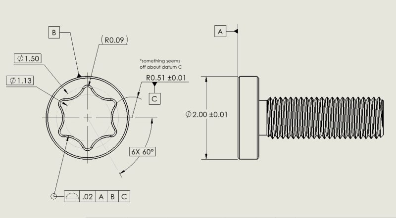
I'm trying to establish if there is a need to establish a datum C for a torx head screw, and how it could be done properly with GDT. My only understanding til this point of leaving out locking down rotation is on purely cylindrical revolved geometry.
I just encountered a torx print that did not have datum C and allow rotational freedom in Z. Maybe this is correct, maybe it is dealers choice, and that is why I'm asking.
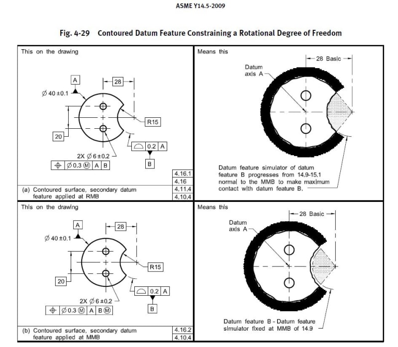
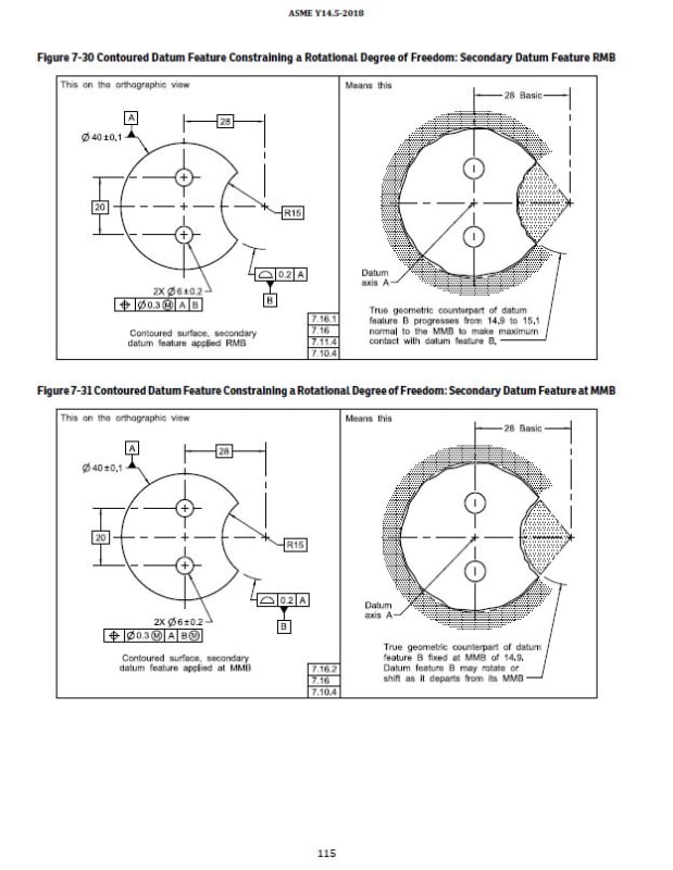
In my attempt to lock down rotation, I attempted to use a radius surface for the datum feature, but when I looked up the standard it shows the radius as a basic dimension then the datum is attached the profile of a surface FCF....both 2009, 2018 standard pics are below....they are in different chapters so I put them below.
If I followed suit into the standard and created datum C from the profile of a surface callout it would conflict with the desired profile callout listed on my print. On the otherhand if datum C is listed as is on my print and I measured this with a CMM and a cad model the profile of a surface could get all messed up depending on the radius.
If I just forgot about datum C and hence rotation and made the radius basic, the problem seems to go away.
I'm confused. Thank for having a look. 2009 Fig. 4-29 & 2018 Fig. 7-30
*edit...the prints I've come across so far with torx like heads use min max diameter as basic dims for the drive head, so I followed suit here.
*edit...the datum surface is not much in terms of degrees....I know that is a problem for cmms,but is there something written about this for the standards?
I just encountered a torx print that did not have datum C and allow rotational freedom in Z. Maybe this is correct, maybe it is dealers choice, and that is why I'm asking.
In my attempt to lock down rotation, I attempted to use a radius surface for the datum feature, but when I looked up the standard it shows the radius as a basic dimension then the datum is attached the profile of a surface FCF....both 2009, 2018 standard pics are below....they are in different chapters so I put them below.
If I followed suit into the standard and created datum C from the profile of a surface callout it would conflict with the desired profile callout listed on my print. On the otherhand if datum C is listed as is on my print and I measured this with a CMM and a cad model the profile of a surface could get all messed up depending on the radius.
If I just forgot about datum C and hence rotation and made the radius basic, the problem seems to go away.
I'm confused. Thank for having a look. 2009 Fig. 4-29 & 2018 Fig. 7-30
*edit...the prints I've come across so far with torx like heads use min max diameter as basic dims for the drive head, so I followed suit here.
*edit...the datum surface is not much in terms of degrees....I know that is a problem for cmms,but is there something written about this for the standards?