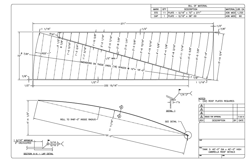
I'm trying to better understand how the roof pieces for an umbrella roof are fabricated. I understand that they are rolled in a single direction and that they are roughly triangular. However, I've also seen references to "gore segment" from IFRs (here) which seems to make sense to me but I'm not sure if it applies here. Here is an example - Let's say I want to fabricate a roof plate. Tank diameter is 50' and umbrella radius is 60. There are 24 segments. There is a 10' diameter compression ring. The dimensions of the sheet steel are as follows:
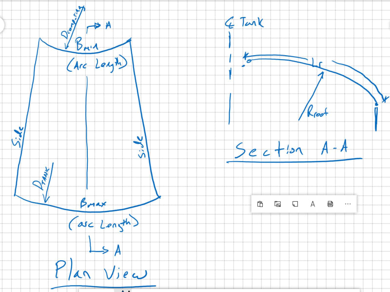
Lr = 20.781' (arc length of sheet steel)
B.max = pi*D.tank/24 = 6.545'
B.min = pi*D.comp_ring/24 =1.309
My question becomes - should the sides of this plate be curved when viewed in plan view or straight? Curved would be like a gore segment (see here). Or, since the plates are only rolled in one direction, is this not required? I suppose the plates will be lapped so there is some tolerance, so I'm curious to know what is "typical" and what is "exact".