VFD MOTOR CONTROL WITH FWD REV AND LIMIT SWITCHES
(OP)
I am considering using a VFD to operate a motor, which is linked by chains and sprockets to an elevating platform.
The platform would need an upper and lower limit switch to prevent it crashing.
I wish for the operator control panel to have just 3 buttons, UP, DOWN and STOP.
I presumed this was a very common application, and thought the wiring would be pretty straight forward, but when I came to draw out a scheme, I got a bit confused.
Then when I looked on line I couldn't find any examples of such a circuit.
Am I wrong to think this is a common set up? I was searching for VFD MOTOR DRIVE WITH LIMIT SWITCHES
The VFD will not be visible to the operator, and will only be accessible and adjustable by myself.
Can anyone point me to such a circuit diagram please.
RE: VFD MOTOR CONTROL WITH FWD REV AND LIMIT SWITCHES
" We are all here on earth to help others; what on earth the others are here for I don't know." -- W. H. Auden
RE: VFD MOTOR CONTROL WITH FWD REV AND LIMIT SWITCHES
ASME B20.1-2021: Safety Standard For Conveyors And Related Equipment
Are you building something like a adjustable height table, or a lift for material (Vertical Reciprocating Conveyor)?
This could also be something similar to a machine tool work table.
The advice of talking to VFD suppliers is sound, You might be able to find a VFD with dry contacts that can be assigned to your buttons, and still have two for the limit switches, Then the VFD needs to have the ability to be programed for the limit switch function.
You also need to think about the safety stop, and particularly what safe state needs to exist once you do a safety stop, and how to initiate one.
RE: VFD MOTOR CONTROL WITH FWD REV AND LIMIT SWITCHES
You have the excitation voltage out of the VFD's low voltage control blocks come out thru the N.C. LATCHING E-STOP switch.
From the other side of the E-Stop it splits into two.
One goes to the upper limit switch.
One goes to the lower limit switch.
The other side of the upper limit switch goes to the UP button.
The other side of the lower limit switch goes to the DOWN button.
The other side of the UP button goes to digital input "1".
The other side of the DOWN button goes to digital input "2".
You then peruse the VFD's manual and make sure it's Digital Inputs "1" is set for forward.
"2" is set for reverse.
While you're at it you have to make sure all the motor settings are correct including the MOTOR FLA being set exactly correct.
You will also need to set the acceleration time.
And, the deceleration time to something shorter than the likely default 10 seconds.
Keith Cress
kcress - http://www.flaminsystems.com
RE: VFD MOTOR CONTROL WITH FWD REV AND LIMIT SWITCHES
Keith Cress
kcress - http://www.flaminsystems.com
RE: VFD MOTOR CONTROL WITH FWD REV AND LIMIT SWITCHES
Thanks for you description.
I already figured out a solution which sounds pretty much like yours, but slightly different.
Do you see any pitfalls in it?
I have already built it and it seems to work fine so far.
RE: VFD MOTOR CONTROL WITH FWD REV AND LIMIT SWITCHES
In a Constant Torque (CT) application, the motor is capable of a 10:1 turn down ratio, meaning if you are going to use it with a VFD, you can turn the speed down to no less than 6hz (60Hz / 10).
In a Variable Torque (VT) application, meaning a centrifugal pump or fan, the maximum turn-down ratio is 20:1, so 3Hz minimum, which is a pointless spec because a centrifugal machine will never be used at that low of a speed.
Per NEMA MG-1 part 30 just means the motor has been designed to meet the performance and construction guidelines set forth in a document put out by NEMA (National Electrical Manufacturer's Association) for Motors and Generators (MG), Specification 1, part 30, which describes general requirements for motors that will be run on inverter drives, entitled;
RE: VFD MOTOR CONTROL WITH FWD REV AND LIMIT SWITCHES
What about driving a reel of paper roll in a packaging facility, which is uncoiling?
Isn't that a variable torque, which could still be used at 3Hz
RE: VFD MOTOR CONTROL WITH FWD REV AND LIMIT SWITCHES
Keith Cress
kcress - http://www.flaminsystems.com
RE: VFD MOTOR CONTROL WITH FWD REV AND LIMIT SWITCHES
I don't know what an obtuse configuration means?
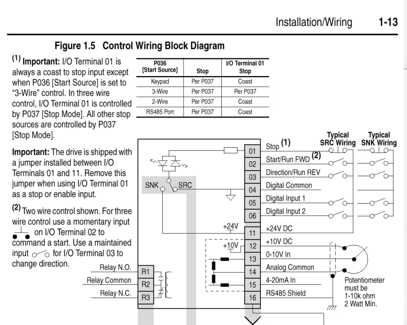
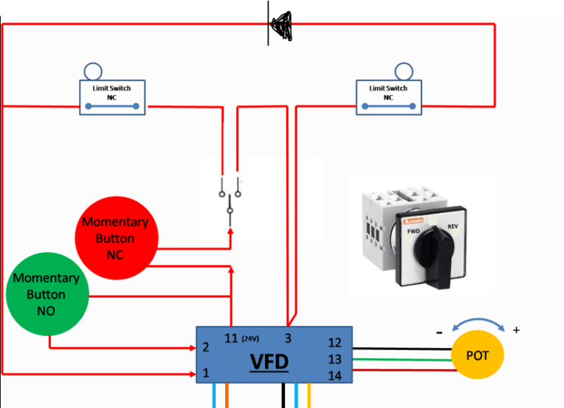
Pin 1 needs to be held HI otherwise the VFD output to the motor is stopped.
Pin 2 needs a momentary HI input to initiate a RUN command
Pin 3 needs to be held HI to maintain a REVERSE RUN command
A depression of either limit switch, or any change in the changeover switch position, or pressing the STOP button, will immediately release Pin 1 from its HI state and stop the VFD output.
It seems pretty simple to me, and it works as expected.
(Obviously the limit switch on the FWD side, can't change the state of Pin 1, while the carriage is selected to go in the REV direction, and vice versa).
Maybe my VFD pin configuration isn't so normal?
Here it is.
RE: VFD MOTOR CONTROL WITH FWD REV AND LIMIT SWITCHES
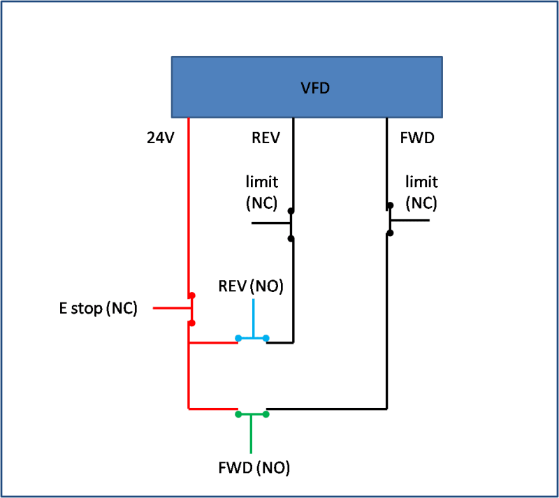
Your 24V would go to an E-STOP(NC) and from the other side of the E-STOP to UP Limit SW(NC) and from E-STOP to DOWN Limit SW(NC).
From the limit switches to their respective UP Button(NO) and DOWN Button(NO).
Then on to their respective Dig INPUTS "FWD" and "REV".
Now if any wire fails to the E-STOP nothing moves.
If any wire breaks between the E-STOP and the FWD or REV inputs (DIG2 or DIG3 on your VFD) the affected direction doesn't move making troubleshooting VERY simple.
On your drive you would wire 24V directly to DIG1.
Parameter wise you would set 2-wire control.
Keith Cress
kcress - http://www.flaminsystems.com
RE: VFD MOTOR CONTROL WITH FWD REV AND LIMIT SWITCHES
So the operator would push a button until the desired up or down position was reached then release the button.
That would tend to be less cumbersome than pressing a latching up or down then waiting to hit a stop button at some correct point in travel. Also a latching situation can cause "unexpected movement". If a latching up or down is used the motion will continue until the limit is reached. If the limit is 'un-reached' because of, say, weight removed from a lift then since the latched direction is still in force the system can unexpectedly go into motion again.
A latched direction switch is not a good motion man-machine setup unless it's a continuous motion like a motor running a process. If you want a latching limited linear motion then it should be an electrically setup latch that self cancels when the limit is reached and definitely not a position latched switch.
Are all movements to the limit always?
Keith Cress
kcress - http://www.flaminsystems.com
RE: VFD MOTOR CONTROL WITH FWD REV AND LIMIT SWITCHES
The need is.
The ability to go from fully up to fully down, and vice versa, at the press of a button, after selecting UP or DOWN on the changeover switch.
(No provision for someone to stand holding a button depressed for 5 minutes is required or feasible. I would class that as cumbersome).
The ability to control speed via a POT.
(There are no humans in the firing line).
That's all.
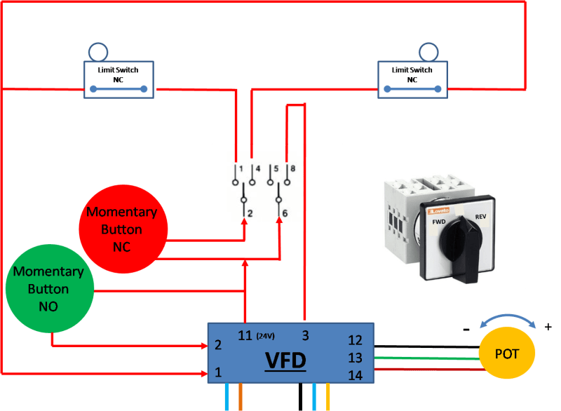
My initial scheme had one part I didn't like, i.e. if the wire to Pin 3 got severed, the travel direction would change, but there would have been no active limit switch in that new direction of travel.
I have modified my scheme so that the if the wire to Pin 3 gets severed, the VFD output will stop, since Pin 1 would no longer be held HI.
See below.
RE: VFD MOTOR CONTROL WITH FWD REV AND LIMIT SWITCHES
I just discovered a bug in my last circuit.
It wouldn't work without a diode as shown below, so I prefer to revert to the previous double pole changeover switch rather than use the diode option.
RE: VFD MOTOR CONTROL WITH FWD REV AND LIMIT SWITCHES
"...I am considering using a VFD to operate a motor, which is linked by chains and sprockets to an elevating platform....The platform would need an upper and lower limit switch to prevent it crashing....I wish for the operator control panel to have just 3 buttons, UP, DOWN and STOP...."
1. Based on your requirement, I propose the control schematic without having a STOP push-button ; whether it suits your application for your consideration .
2. Operation procedure:
.1 switch on, motor does NOT move.
.2 Press UP push-button, the load moves up direction. Release the Up push-button, the load stops at any position. Continuously pressing the Up push-button, the load goes up to the upper limit and stops automatically; prevent it crashing.
.3 Press Down push-button, the load moves down direction. Release the Down push-button, the load stops at any position. Continuously pressing the Down push-button, the load goes down to the lower limit and stops automatically; prevent it crashing.
3. Pressing (Up+Down) both push-buttons together does NOT cause the motor to move. No damage either.
4. Press the E-stop (self latching) push-button stops the motor, irrespective of whether the motor is moving up or down.
5. Unlatch the E-stop push-button by [Twist or pull] as applicable.
Che Kuan Yau (Singapore)
RE: VFD MOTOR CONTROL WITH FWD REV AND LIMIT SWITCHES
Thanks for taking time to share your thoughts and your scheme.
My system needs a stop button, because holding the button in for long periods is not practical.
But I have created a circuit something like yours for a different job before.
I used a pendant with two buttons, and an E stop, so it made it very simple, because the two momentary buttons inside the pendant are configured, so that only one button can be pressed at one time. The mechanical systems inside prevents two buttons creating a contact simultaneously. That made the circuit very simple indeed. So this is a press and hold arrangement, with limit switches. See below
(P.S. If I just edit the scheme below to have two mutually exclusive latching switches for FWD and REV, instead of momentary NO, then it suits my other application also).
The pendant is a Schneider XACA2713