×
INTELLIGENT WORK FORUMS
FOR ENGINEERING PROFESSIONALS

Contact US

Log In

Come Join Us!

Are you an
Engineering professional?
Join Eng-Tips Forums!
  • Talk With Other Members
  • Be Notified Of Responses
    To Your Posts
  • Keyword Search
  • One-Click Access To Your
    Favorite Forums
  • Automated Signatures
    On Your Posts
  • Best Of All, It's Free!

*Eng-Tips's functionality depends on members receiving e-mail. By joining you are opting in to receive e-mail.

Posting Guidelines

Promoting, selling, recruiting, coursework and thesis posting is forbidden.

Students Click Here

Difference between the different von mises?

Difference between the different von mises?

Difference between the different von mises?

(OP)
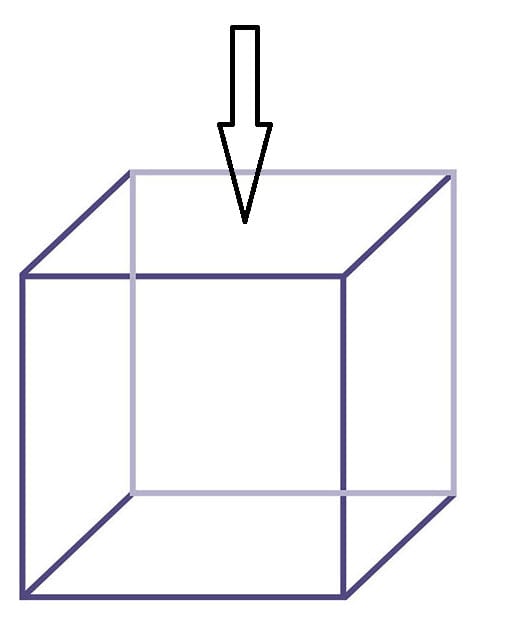
My FEA software gives me the option of looking at top, membrane, bottom and max von mises stress. If I have for example a cube, and load applied in the middle at the top, and I want to find the highest point of stress in the plates below (not top plate), which von mises stress should I look at?


RE: Difference between the different von mises?

Which software do you use ? These output are likely explained in the documentation but generally speaking they refer to shell and beam elements having multiple integration points (or section points) through the thickness. For solid elements it's not relevant.

RE: Difference between the different von mises?

(OP)
These are all 2D shell rectangular elements. Its not a popular programme I am using, its limited in its use, I dont think its possible to even use solid elements. With this being said, which von mises would you guess would be correct to use?

Also Ive been told to make the top plate thick, as it will distribute the loads more equally to the plates below - why is it that thick plates distribute load more equally than thin plates?

RE: Difference between the different von mises?

I would choose max since it's the type of output that we usually want to get. To clarify, this setting refers to individual shell elements so for example, top doesn't mean that you won't get output for the bottom plate.

Can you say more about the model ? The thickness of shell elements should depend on the dimensions of the actual structure. But it can be easily changed so you can try with different values and see how they affect the results.

RE: Difference between the different von mises?

a 2D shell still has bending, so top surface stress is not necessarily the same as bottom surface.

another day in paradise, or is paradise one day closer ?

RE: Difference between the different von mises?

in your example, I'd expect the highest stress would be on the top face, bottom surface (as the face has thickness, and a top surface and a bottom surface), near the load where the face has maximum bending.

another day in paradise, or is paradise one day closer ?

RE: Difference between the different von mises?

Top-plate top surface stress
Membrane- plate mid surface stress
Bottom- plate bottom surface stress
Max-most probably max value of stress between two-top and bottom surface

To check which plate has max stress, plot max stress( if above is true).

If the cube is made up of 6 faces with thickness and modelled as hollow shell cube , and you are applying load at the top face, I would expect the top plate to undergo bending, the vertical plates to undergo bending + axial compression and bottom plate to undergo compression.

Most probably stress will be max at the top plate(plate where load is applied)-top surface.

RE: Difference between the different von mises?

some programs display the VM as the surface that is visible so rotate model and see stress on other side

Red Flag This Post

Please let us know here why this post is inappropriate. Reasons such as off-topic, duplicates, flames, illegal, vulgar, or students posting their homework.

Red Flag Submitted

Thank you for helping keep Eng-Tips Forums free from inappropriate posts.
The Eng-Tips staff will check this out and take appropriate action.

Reply To This Thread

Posting in the Eng-Tips forums is a member-only feature.

Click Here to join Eng-Tips and talk with other members! Already a Member? Login


Resources

Low-Volume Rapid Injection Molding With 3D Printed Molds
Learn methods and guidelines for using stereolithography (SLA) 3D printed molds in the injection molding process to lower costs and lead time. Discover how this hybrid manufacturing process enables on-demand mold fabrication to quickly produce small batches of thermoplastic parts. Download Now
Design for Additive Manufacturing (DfAM)
Examine how the principles of DfAM upend many of the long-standing rules around manufacturability - allowing engineers and designers to place a part’s function at the center of their design considerations. Download Now
Taking Control of Engineering Documents
This ebook covers tips for creating and managing workflows, security best practices and protection of intellectual property, Cloud vs. on-premise software solutions, CAD file management, compliance, and more. Download Now

Close Box

Join Eng-Tips® Today!

Join your peers on the Internet's largest technical engineering professional community.
It's easy to join and it's free.

Here's Why Members Love Eng-Tips Forums:

Register now while it's still free!

Already a member? Close this window and log in.

Join Us             Close