MrAtkinson
Mechanical
Hi all,
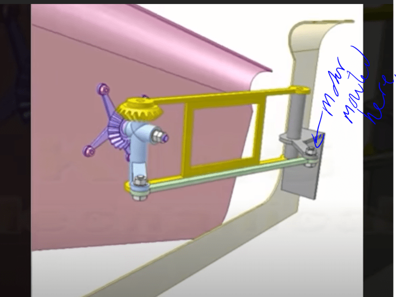
I wanted to ask if an idea i have had is possible/if its the best way to do it. I am looking to push a panel which will weigh around 125lb to a specific distance (around 100mm) and then rotate the panel from the bottom corner 90 degrees up. I was originally thinking of having a linear actuator to push the panel out using a part geared shaft/spur gear, part round bar (i will call it the axle) and then have a Nema 34 motor with gears mounted to turn the shaft and rotate the panel.
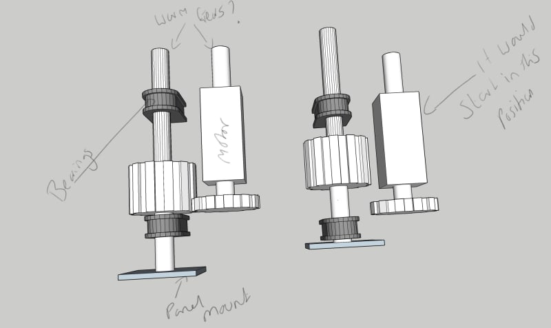
I then thought, would it be possible to eliminate the linear actuator and use a dual shaft nema motor. One end of the motor shaft has the gear to make the rotation but utilising a worm gear on the other end to push the axle forward. So essentially the motor spins the front gear and the worm gear at the same time, the worm gear pushes the axle forward to push the panel out 100mm but at a specific point of the linear motion of the axle the section of the axle that has the accepting gear interlocks with the gear on the other end of the motor and rotates which in turn rotates the panel.
I have created a very quick 3d model to give an idea of what I'm thinking of, nothing is to scale, its simply for visual reference. I've also attached the .skp file of the model in case its helpful.
I am self taught in this stuff so please bear with me if I have missed something obvious or over engineered it.
My questions are, would this be a viable way to do it? would I be able to get the worm gear to work with the shaft in parallel or would using a 90degree gear change be a better solution? OR does anyone know of a better way to do it?
Thanks
Jake
[URL unfurl="true"]https://res.cloudinary.com/engineering-com/raw/upload/v1641418435/tips/HInge_nqmw5o.skp[/url]
I wanted to ask if an idea i have had is possible/if its the best way to do it. I am looking to push a panel which will weigh around 125lb to a specific distance (around 100mm) and then rotate the panel from the bottom corner 90 degrees up. I was originally thinking of having a linear actuator to push the panel out using a part geared shaft/spur gear, part round bar (i will call it the axle) and then have a Nema 34 motor with gears mounted to turn the shaft and rotate the panel.
I then thought, would it be possible to eliminate the linear actuator and use a dual shaft nema motor. One end of the motor shaft has the gear to make the rotation but utilising a worm gear on the other end to push the axle forward. So essentially the motor spins the front gear and the worm gear at the same time, the worm gear pushes the axle forward to push the panel out 100mm but at a specific point of the linear motion of the axle the section of the axle that has the accepting gear interlocks with the gear on the other end of the motor and rotates which in turn rotates the panel.
I have created a very quick 3d model to give an idea of what I'm thinking of, nothing is to scale, its simply for visual reference. I've also attached the .skp file of the model in case its helpful.
I am self taught in this stuff so please bear with me if I have missed something obvious or over engineered it.
My questions are, would this be a viable way to do it? would I be able to get the worm gear to work with the shaft in parallel or would using a 90degree gear change be a better solution? OR does anyone know of a better way to do it?
Thanks
Jake
[URL unfurl="true"]https://res.cloudinary.com/engineering-com/raw/upload/v1641418435/tips/HInge_nqmw5o.skp[/url]