×
INTELLIGENT WORK FORUMS
FOR ENGINEERING PROFESSIONALS

Contact US

Log In

Come Join Us!

Are you an
Engineering professional?
Join Eng-Tips Forums!
  • Talk With Other Members
  • Be Notified Of Responses
    To Your Posts
  • Keyword Search
  • One-Click Access To Your
    Favorite Forums
  • Automated Signatures
    On Your Posts
  • Best Of All, It's Free!

*Eng-Tips's functionality depends on members receiving e-mail. By joining you are opting in to receive e-mail.

Posting Guidelines

Promoting, selling, recruiting, coursework and thesis posting is forbidden.

Students Click Here

Full height concrete abutment walls subjected to scour

Full height concrete abutment walls subjected to scour

Full height concrete abutment walls subjected to scour

(OP)
We have been tasked to design full height concrete abutments on spread footings subjected to scour. The bridge structure will be an ACROW steel bridge similar to a Bailey bridge. The single span is 110 feet from CL bearing to CL bearing with HL-93 loading. My question concerns scour from stream flow. During the scour condition the depth of flow down to the scour elevation is 15 feet. I plan on setting the tops of the spread footing 2 to 3 feet below the scour elevation. Of course the backfill behind the wall remains. Do I design the wall with the active backfill soil load and traffic surcharge load acting on the back side of the wall and the hydrostatic stream flow pressure acting on the other side of the wall? Do they act simultaneously and use the resulting loads to the design the concrete stem?

I never have encountered this condition before since I have always used stub abutments founded on drilled shafts.

Any help would and suggestions will be greatly appreciated

Thank You

RE: Full height concrete abutment walls subjected to scour

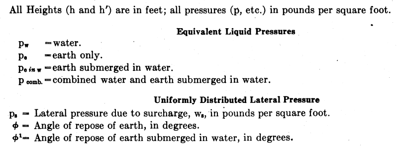
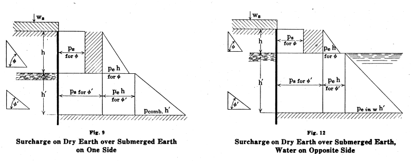
minorchord2000 - I believe the soil/water pressure diagram is more complex, with submerged earth on one side. I would consider both Figure 9 and Figure 12 (shown below), with Figure 9 (no water in the stream and submerged earth behind the wall being the upper bound. Figure 12 (water in the stream and submerged earth behind the wall) being the lower bound.


Those footings will be really expensive, appears a 30'+ deep cofferdam will be required to construct each one.

www.SlideRuleEra.net

RE: Full height concrete abutment walls subjected to scour

wow, you are in for some fun. You are going to have really large heels to resist that all that earth pressure. The last time I needed to design an abutment that tall we had huge footings.

Are deep foundation an option, I suspect with that potential much scour they should be. You could also do a shorter stub abutment on piles and wrap it with sheet piles. Considering you will need to drive sheet piles to construct this, it might be a more cost effective option.

RE: Full height concrete abutment walls subjected to scour

I have a question on this though:
When a particular scour depth is provided as in the sketch above, how do we determine the extent of wingwall, as scour does not only happen in front of the abutment (horizontal extent of scour back of the abutment). We need to retain earth and protect the approaches behind.

If you can do a plate model with wingwalls (a rigid abutment), the wingwalls would help reduce demands on the stem wall. Note that earth pressure considered for rigid abutments are higher compared to flexible cantilever retaining walls for example.

RE: Full height concrete abutment walls subjected to scour

Depending on how quickly the stream level in front of the wall fluctuates, you may have to consider the differential in water pressure due to what's called rapid drawdown.

The last time I faced a situation like this (on a somewhat smaller scale), I put 30" drilled shafts directly under the 36" wide abutment wall and sweptback wingwalls. The DS under the abutment wall provided bearing capacity for the superstructure loads and downward load from the overturning moment, while the DS at the ends of the wingwalls provided the uplift resistance for overturning.

Rod Smith, P.E., The artist formerly known as HotRod10

Red Flag This Post

Please let us know here why this post is inappropriate. Reasons such as off-topic, duplicates, flames, illegal, vulgar, or students posting their homework.

Red Flag Submitted

Thank you for helping keep Eng-Tips Forums free from inappropriate posts.
The Eng-Tips staff will check this out and take appropriate action.

Reply To This Thread

Posting in the Eng-Tips forums is a member-only feature.

Click Here to join Eng-Tips and talk with other members! Already a Member? Login


Resources

Low-Volume Rapid Injection Molding With 3D Printed Molds
Learn methods and guidelines for using stereolithography (SLA) 3D printed molds in the injection molding process to lower costs and lead time. Discover how this hybrid manufacturing process enables on-demand mold fabrication to quickly produce small batches of thermoplastic parts. Download Now
Design for Additive Manufacturing (DfAM)
Examine how the principles of DfAM upend many of the long-standing rules around manufacturability - allowing engineers and designers to place a part’s function at the center of their design considerations. Download Now
Taking Control of Engineering Documents
This ebook covers tips for creating and managing workflows, security best practices and protection of intellectual property, Cloud vs. on-premise software solutions, CAD file management, compliance, and more. Download Now

Close Box

Join Eng-Tips® Today!

Join your peers on the Internet's largest technical engineering professional community.
It's easy to join and it's free.

Here's Why Members Love Eng-Tips Forums:

Register now while it's still free!

Already a member? Close this window and log in.

Join Us             Close