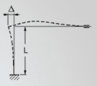
There's decent formulas and rules of the thumb about for using 90° bends to absorb thermal expansion in pipelines.
How to account for this shape:
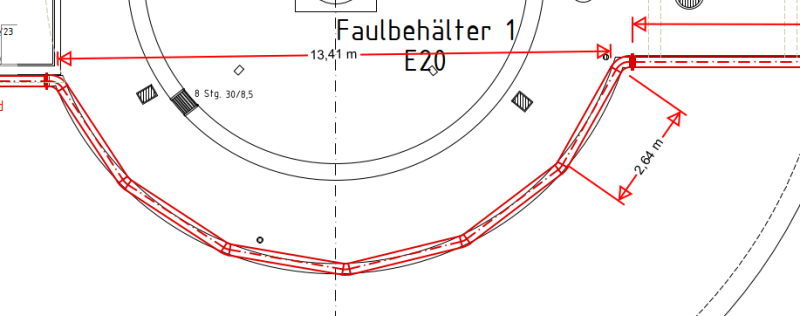
The pipeline follows the parapet on the top of a series of vessels.
the pipe is stainless steel, DN 250, to the left it's ~7m to a fixed point (pipe runs through hole in ground) to the right it's ~16m to the next semicircle like the one in the picture. there are four more similar arches long the pipeline
I need to account for 1mm/m of thermal expansion.
I want to avoid expansion joints.
Surely at these obtuse angels these arches are not as good at absorbing expansion as a 90° bend with a long enough leg would be.
My first idea is to fix the middle of the arches and middle of the long segments, using 2D gliding supports in between (stainless steel supports on PTFE). what would be the peak stress in the pipeline due to thermal expansion?
How to account for this shape:
The pipeline follows the parapet on the top of a series of vessels.
the pipe is stainless steel, DN 250, to the left it's ~7m to a fixed point (pipe runs through hole in ground) to the right it's ~16m to the next semicircle like the one in the picture. there are four more similar arches long the pipeline
I need to account for 1mm/m of thermal expansion.
I want to avoid expansion joints.
Surely at these obtuse angels these arches are not as good at absorbing expansion as a 90° bend with a long enough leg would be.
My first idea is to fix the middle of the arches and middle of the long segments, using 2D gliding supports in between (stainless steel supports on PTFE). what would be the peak stress in the pipeline due to thermal expansion?
![[lookaround]](/data/assets/smilies/lookaround.gif "[lookaround] [lookaround]")