PaulKraemer
Electrical
Hi,
I have a tank that is used to melt glue. It has six heaters, each with a resistance of 10 ohms. It is powered with 208 VAC three phase.
Originally, it was wired as shown below with two heaters in parallel across each possible pair of lines (L1-L2, L2-L3, and L1-L3)...
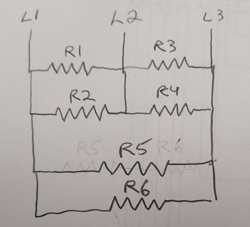
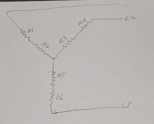
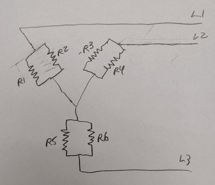
I had asked a question yesterday about how to calculate the total current that this circuit would draw from L1, L2, and L3, which turned out to be about 72 amps. It turns out that this exceeds the rating of the breakers I have available to feed this circuit. With this being the case, I considered rewiring the heaters as shown below to reduce the current draw ...
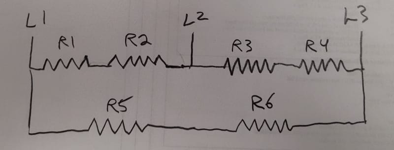
... When I did the same current calculations (if I did them correctly), this decreased my expected current by a factor of four (down to 18 amps). This would make it easy for me to find a breaker to serve the circuit, but I am afraid that the corresponding factor of four decrease in heating power might make me unable to melt glue at my required rate.
I am wondering if anyone here can suggest another wiring alternative that would allow me to decrease the current draw by a factor that is less than four while still keeping my load balanced and having the same current flowing through every heater. I though about simply eliminating three heaters so that I would only hava a single heater across each possible pair of lines (L1-L2, L2-L3, and L1-L3), but I don't like this idea because it would mean I would then have less heated surface area in contact with the glue. I would really like to have current (albeit reduced) flowing through all six heaters. With six heaters and three lines, I just can't think of a way I can do this other than how I show in my second diagram (which results in a 4x reduction in power).
Any suggestions will be greatly appreciated.
Thanks and best regards,
Paul
I have a tank that is used to melt glue. It has six heaters, each with a resistance of 10 ohms. It is powered with 208 VAC three phase.
Originally, it was wired as shown below with two heaters in parallel across each possible pair of lines (L1-L2, L2-L3, and L1-L3)...
I had asked a question yesterday about how to calculate the total current that this circuit would draw from L1, L2, and L3, which turned out to be about 72 amps. It turns out that this exceeds the rating of the breakers I have available to feed this circuit. With this being the case, I considered rewiring the heaters as shown below to reduce the current draw ...
... When I did the same current calculations (if I did them correctly), this decreased my expected current by a factor of four (down to 18 amps). This would make it easy for me to find a breaker to serve the circuit, but I am afraid that the corresponding factor of four decrease in heating power might make me unable to melt glue at my required rate.
I am wondering if anyone here can suggest another wiring alternative that would allow me to decrease the current draw by a factor that is less than four while still keeping my load balanced and having the same current flowing through every heater. I though about simply eliminating three heaters so that I would only hava a single heater across each possible pair of lines (L1-L2, L2-L3, and L1-L3), but I don't like this idea because it would mean I would then have less heated surface area in contact with the glue. I would really like to have current (albeit reduced) flowing through all six heaters. With six heaters and three lines, I just can't think of a way I can do this other than how I show in my second diagram (which results in a 4x reduction in power).
Any suggestions will be greatly appreciated.
Thanks and best regards,
Paul