×
INTELLIGENT WORK FORUMS
FOR ENGINEERING PROFESSIONALS

Contact US

Log In

Come Join Us!

Are you an
Engineering professional?
Join Eng-Tips Forums!
  • Talk With Other Members
  • Be Notified Of Responses
    To Your Posts
  • Keyword Search
  • One-Click Access To Your
    Favorite Forums
  • Automated Signatures
    On Your Posts
  • Best Of All, It's Free!

*Eng-Tips's functionality depends on members receiving e-mail. By joining you are opting in to receive e-mail.

Posting Guidelines

Promoting, selling, recruiting, coursework and thesis posting is forbidden.

Students Click Here

Modeling Heat Exchanger Sections

Modeling Heat Exchanger Sections

Modeling Heat Exchanger Sections

(OP)
Hi,

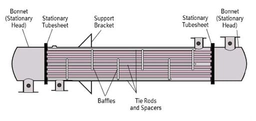
Is it a valid assumption to model sections of a heat exchanger individually for an explosive event? In the picture below, if rupture takes place in the head, is it appropriate to ignore the shell side as the tubesheet would isolate the explosion within the head? For those experienced with hydrocarbon explosions, does the tubesheet do a good job of completely isolating the forces of an explosion?

RE: Modeling Heat Exchanger Sections

If you are not sure which parts to include in the model, try several levels of simplification. It will be interesting to see how this influences the results. But with proper boundary conditions it’s likely that you won’t have to model the rest of the structure.

RE: Modeling Heat Exchanger Sections

(OP)
@FEA way, I have old hardware (a 5 year old, 4 core workstation), so a suggestion was made to model the head separately. Based on the limited number of research articles on the subject, it appears that the tubesheet isolates an explosion in the head or shell (ex. PVP2014-28893). Note: This is a training exercise.

RE: Modeling Heat Exchanger Sections

Hi!
I agree with FEA way. Start with the Head alone if you think the phenomenon is confined to that single item. Take some time for thinking how to model proper Boundary Conditions.
Do you have any result benchmark to compare your results to? That will guide you (sort of).
If you don't get a correct answer, then check BCs and loads. If they are correct it means you have to model a further section.
This is the first time I see this problem but when investigating impacts against some kind of structure this was the only approach which worked.

Red Flag This Post

Please let us know here why this post is inappropriate. Reasons such as off-topic, duplicates, flames, illegal, vulgar, or students posting their homework.

Red Flag Submitted

Thank you for helping keep Eng-Tips Forums free from inappropriate posts.
The Eng-Tips staff will check this out and take appropriate action.

Reply To This Thread

Posting in the Eng-Tips forums is a member-only feature.

Click Here to join Eng-Tips and talk with other members! Already a Member? Login


Resources

Low-Volume Rapid Injection Molding With 3D Printed Molds
Learn methods and guidelines for using stereolithography (SLA) 3D printed molds in the injection molding process to lower costs and lead time. Discover how this hybrid manufacturing process enables on-demand mold fabrication to quickly produce small batches of thermoplastic parts. Download Now
Design for Additive Manufacturing (DfAM)
Examine how the principles of DfAM upend many of the long-standing rules around manufacturability - allowing engineers and designers to place a part’s function at the center of their design considerations. Download Now
Taking Control of Engineering Documents
This ebook covers tips for creating and managing workflows, security best practices and protection of intellectual property, Cloud vs. on-premise software solutions, CAD file management, compliance, and more. Download Now

Close Box

Join Eng-Tips® Today!

Join your peers on the Internet's largest technical engineering professional community.
It's easy to join and it's free.

Here's Why Members Love Eng-Tips Forums:

Register now while it's still free!

Already a member? Close this window and log in.

Join Us             Close