×
INTELLIGENT WORK FORUMS
FOR ENGINEERING PROFESSIONALS

Log In

Come Join Us!

Are you an
Engineering professional?
Join Eng-Tips Forums!
  • Talk With Other Members
  • Be Notified Of Responses
    To Your Posts
  • Keyword Search
  • One-Click Access To Your
    Favorite Forums
  • Automated Signatures
    On Your Posts
  • Best Of All, It's Free!

*Eng-Tips's functionality depends on members receiving e-mail. By joining you are opting in to receive e-mail.

Posting Guidelines

Promoting, selling, recruiting, coursework and thesis posting is forbidden.

Students Click Here

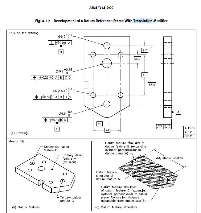
Fig. 4-19 Development of a Datum Reference Frame With Translation Modifier ASME-14.5 2009

Fig. 4-19 Development of a Datum Reference Frame With Translation Modifier ASME-14.5 2009

Replies continue below

Recommended for you

RE: Fig. 4-19 Development of a Datum Reference Frame With Translation Modifier ASME-14.5 2009

In the example the translation modifier is used because there is no useful calculation to do without it.

It's like asking why a knight on a chessboard does not move diagonally.

The ASME Y14.5 committee decided to add the translation modifier for cases when there isn't an MMC modifier that would allow the use of fixed size gage pins for the datums.

In previous versions some ASME Y14.5 committee members claimed that an over-constrained DRF was "obviously" one that demanded the over-constraints must be ignored. With the translation modifier they are explicitly saying the over-contraint should be ignored.

Datum feature A planar surface controls 3 degrees of freedom, the RFS datum feature B pin controls 2 degrees of freedome, and the RFS datum feature C controls 2 degrees of freedom. That is a total of 7 degrees of freedom. The part is a rigid prismatic solid so there are only 6 degrees of freedom available, so the translation modifier throws away one of them for the datum feature C pin.

If that degree of freedom was not thrown out, the pins on the fixture would be a fixed distance apart and the item being inspected would have to be elastically stretched or compressed to get the holes to a matching location, possibly requiring a Finite Element Analysis to determine all the distortions that would result from that.

Almost any calculation would involve a matrix of inequalities to describe even trivial ones.
RE: Fig. 4-19 Development of a Datum Reference Frame With Translation Modifier ASME-14.5 2009

(OP)
Thank you 3DDAve

Red Flag This Post

Please let us know here why this post is inappropriate. Reasons such as off-topic, duplicates, flames, illegal, vulgar, or students posting their homework.

Red Flag Submitted

Thank you for helping keep Eng-Tips Forums free from inappropriate posts.
The Eng-Tips staff will check this out and take appropriate action.

Reply To This Thread

Posting in the Eng-Tips forums is a member-only feature.

Click Here to join Eng-Tips and talk with other members! Already a Member? Login


News


Close Box

Join Eng-Tips® Today!

Join your peers on the Internet's largest technical engineering professional community.
It's easy to join and it's free.

Here's Why Members Love Eng-Tips Forums:

Register now while it's still free!

Already a member? Close this window and log in.

Join Us             Close