Local failure assessment of nozzle junctions - weld sharp edges
(OP)
Hi, i need to analyze the nozzle junction of a pressure vessel (designed by ASME XIII div. 1) according to appendix 46 (following the steps of div. 2 part 5).
i am using an elastic plastic model.
i´ve searched a lot of threads of this subject but none of them answers my particular inquiry:
when modeling the welds with sharp edges, there is a stress singularity and of course the stress and strains do not converge to a value when refining the mesh. even though for plastic collapse failure mode it is possible to ignore this effect, when analyzing local failure it is problematic, as there will always be large and unrelistic plastic strains that surpass the allowable by the code.
it is not possible to model a fillet radius since it is not known, besides of producing a huge computational cost.
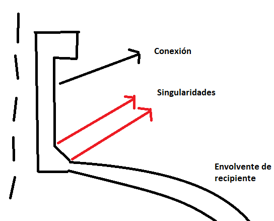
the following image ilustrates the situation.
how can i verify this failure mode in this contion?
thanks in advance
i am using an elastic plastic model.
i´ve searched a lot of threads of this subject but none of them answers my particular inquiry:
when modeling the welds with sharp edges, there is a stress singularity and of course the stress and strains do not converge to a value when refining the mesh. even though for plastic collapse failure mode it is possible to ignore this effect, when analyzing local failure it is problematic, as there will always be large and unrelistic plastic strains that surpass the allowable by the code.
it is not possible to model a fillet radius since it is not known, besides of producing a huge computational cost.
the following image ilustrates the situation.

how can i verify this failure mode in this contion?
thanks in advance
RE: Local failure assessment of nozzle junctions - weld sharp edges
- add fillet
- include plasticity
- ignore it and read results from different location
In this case you considered all these approaches. But keep in mind that the analysis with plasticity included is not unrealistic as in real life notches like that will also cause large stress concentrations and local yielding. But usually this yielding is limited to really small area and doesn’t indicate failure.
There are also special methods for weld assessment designed to bypass stress singularities. These approaches include hot-spot stress method and structural stress method. They are very useful when determining fatigue life of the weld.
RE: Local failure assessment of nozzle junctions - weld sharp edges
Perhaps i was not clear enough, but what i mean is that according to paragraph 5.3.3.1 (see image) the local failure criteria must be met for all points in the model, this includes de weld edges.
Since the plastic strains near the edge are too high, this criterion will never be met there.
RE: Local failure assessment of nozzle junctions - weld sharp edges
if you model the weld as a (circular) fillet (rad) then even with linear material I doubt you'll see an "issue".
if you model with non-linear material and a chamfer then you'll see highly localised yielding at the weld transition (kink).
"at every point" is something that'd be written in a textbook. "at every significant point" is more real, but opens the discussion to "what's significant ?"
another day in paradise, or is paradise one day closer ?
RE: Local failure assessment of nozzle junctions - weld sharp edges
Would you model as a weld sitting on top of the plate, 2 solid elements ... a brick and a wedge, or would the weld material be essentially part of the plate, 1 solid element ... a tapering brick ?
another day in paradise, or is paradise one day closer ?
RE: Local failure assessment of nozzle junctions - weld sharp edges
Plus, at your "singularity" point, one of the principal stresses is zero, so your triaxiality is low.
How are you calculating your limiting plastic stain, or better yet, how are you calculating your SLDR (strain limit damage ratio)?
RE: Local failure assessment of nozzle junctions - weld sharp edges
i´m not sure if this answers your question
RE: Local failure assessment of nozzle junctions - weld sharp edges
From the paper: So, are you following the advice recommended in the final paragraph I quoted above?
RE: Local failure assessment of nozzle junctions - weld sharp edges
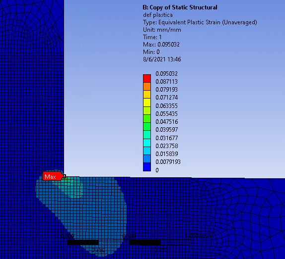
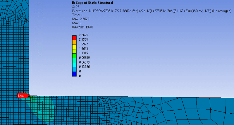
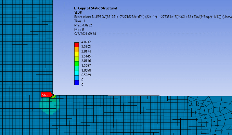
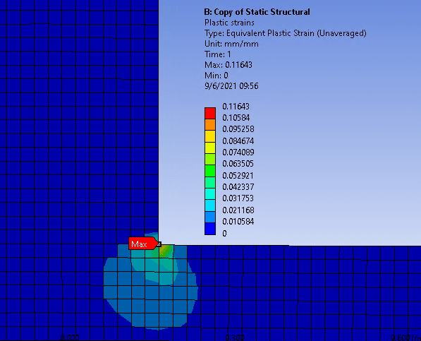
the following images shows the Plastic strain and the SLDR respectively:
Plastic strain (zoom in the zone of interest)
SLDR
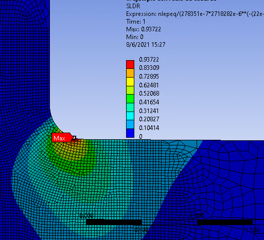
As you can see, there is a zone with SLDR values greater than 1. So i modeled a 0.1 and 0.2 mm raidus but still the SLDR was greater than 1 there. Only with a 0.3 mm radius the SLDR was greater than 1 at each point.
My conclusion is that, when analyzing local failure, modeling the fillet radius is a must, otherwise you can´t be sure that he criteria is satisfied near the weld edges.
RE: Local failure assessment of nozzle junctions - weld sharp edges
Nice idea, modelling simple examples. Have you tried different angles ?
For example, how about adding a chamfer to the corner (to simulate the weld).
How are you modelling the non-homogenous nature of the weld ... the parent material, the heat affected zone, the weld material ??
What's "SDLR" ?
This is the impracticality of "at every point". Every structure has always had details beyond yield. Only they are highly localised and had viable loadpaths around them and so do not hazard the safety of the structure; unless it fatigues.
another day in paradise, or is paradise one day closer ?
RE: Local failure assessment of nozzle junctions - weld sharp edges
SLDR is a term that I invented, called the Strain Limit Damage Ratio, which is the ratio of the calculated equivalent plastic strain divided by the limiting plastic strain, as described in Equation 5.6 of ASME Section VIII, Division 2, Part 5 (and shown above in one of fem.fan's posts.
This relates to a very specific failure mode where, under certain stress states (high triaxiality), the material behaviour transitions from ductile (and represented by the elastic-plastic stress-strain curve) to be more brittle (the limiting plastic strain decreases). It needs to be assessed everywhere, because brittle fractures can occur spontaneously with only one application of a load. I'd be happy to discuss the failure mode in greater detail, if you would like. It's rather fascinating.
RE: Local failure assessment of nozzle junctions - weld sharp edges
the material is SA-516 Gr. 70
αsl = 2.2
m2= 0.2784
FYI, the following image shows the SLDR of the exat same model with the only difference of a 0.3 mm radius.
RE: Local failure assessment of nozzle junctions - weld sharp edges
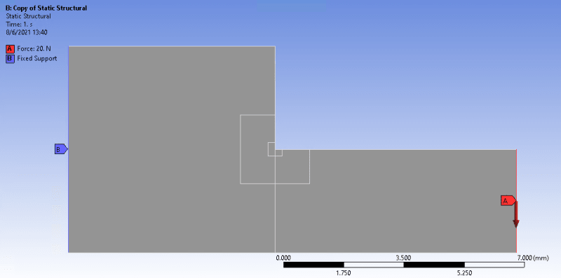
Is your 2D model really 14mm x 7mm with a 7mm x 3.5mm chunk cut out? And a 20N force?
Details, please.
RE: Local failure assessment of nozzle junctions - weld sharp edges
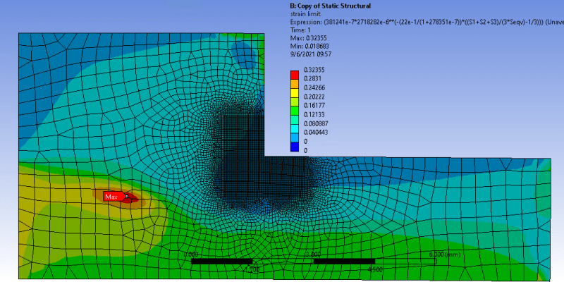
The uniaxial strain limit is 0.381. Why do you say it´s too low? i computed it from table 5.7
the force is 80 N (i changed it because i also changed the yield strength that i had reduced for testing purposes).
updated results:
SLDR
Plastic strains
Strain limit:
RE: Local failure assessment of nozzle junctions - weld sharp edges
Have you done a comparison of the averaged and un-averaged plots of SLDR? Is you mesh converged for SLDR? Remember that apparent convergence for stress and stress does not equate to convergence for SLDR.
I wil admit that I have not run into this problem in my 15+ years doing these types of analyses. Don't forget that your load factor for checking local failure is not β, but only 1.7.
RE: Local failure assessment of nozzle junctions - weld sharp edges
The mesh is converged only "certain distance away" from the singularity. In this particular example let´s say 0.2 mm, but you will never get convergence on the singularity and it´s near vicinity by definition, the stress and strains grow indefinitely there. This is a numerical problem, no matter what load factor you use.
Remember that i made this simulation only as an example, my concern is general.
RE: Local failure assessment of nozzle junctions - weld sharp edges
another day in paradise, or is paradise one day closer ?
RE: Local failure assessment of nozzle junctions - weld sharp edges
One additional note - I do not believe that a bi-linear curve is appropriate here. You will need to upgrade your software. But good for you for trying out the elastic-plastic analysis method.
Happy to help in any way.
RE: Local failure assessment of nozzle junctions - weld sharp edges
If you go to metal forming (deep drawing, wire extrusion, etc) formulae, you will find very similar equations for strain limits. In conditions of high compressive triaxiality, the strain limit can be many multiples of the uniaxial strain limit. (Think of successively drawing a wire from a rough billet). However, in conditions of high tensile triaxiality, the opposite happens - the strain limit decreases until the material is effectively brittle.
This condition is relevant because in the limit of pure triaxiality, the stress invariant (which is based on the difference between the principal stresses - could be von Mises, could even be Tresca) collapses to zero, even though there are non-zero principal stresses. At the limit of pure triaxiality, when the material is ideally brittle, the stress of interest is no longer the invariant (usually von Mises in a ductile material), but the maximum principal stress. However, you need to be able to figure out when that switch-over happens. The ASME Code has a prescribed limit, defined in Equation 5.6. There have been real failures that can be attributed to this failure mode - hence its inclusion in the ASME Code starting in the 2007 Edition. However, the numerical issue (invariant going to zero) was recognized waaaay back when the ASME Code first introduced Design By Analysis in the inaugural (1968) Edition of ASME Section VIII, Division 2 and ASME Section III.
RE: Local failure assessment of nozzle junctions - weld sharp edges
another day in paradise, or is paradise one day closer ?
RE: Local failure assessment of nozzle junctions - weld sharp edges
SLDR
Plastic strain
limit strain
the same with 3mm radius
SLDR
plastic strain
limit strain
RE: Local failure assessment of nozzle junctions - weld sharp edges
I'm late to this discussion, but I've run into this as well. I once ran a model of a lightly loaded sharp inside corner down to an absurdly fine mesh size and found that the stress and plastic strain increased slowly and steadily at an increasing rate with diminishing element edge length, but the plastic strain is extremely localized. I generally ignore this unless there are more generalized triaxial stresses in the area.
Of course, sharp inside corners in ugly welds do cause failures. Typically undercut, overlap, convex fillets, moreso than sharp toes on 45 degree fillets. My advice is that you focus on getting good welds, and don't worry too much about the numerical singularity. If there is a larger volume that is near the strain limit, I might grind the weld toe to make sure I get a smooth transition. If it's a critical service, I might also do a fracture mechanics calculation to understand how likely a crack is to run from the weld toe. Fracture mechanics is better suited to dealing with the singularity.
-mskds545