×
INTELLIGENT WORK FORUMS
FOR ENGINEERING PROFESSIONALS

Log In

Come Join Us!

Are you an
Engineering professional?
Join Eng-Tips Forums!
  • Talk With Other Members
  • Be Notified Of Responses
    To Your Posts
  • Keyword Search
  • One-Click Access To Your
    Favorite Forums
  • Automated Signatures
    On Your Posts
  • Best Of All, It's Free!

*Eng-Tips's functionality depends on members receiving e-mail. By joining you are opting in to receive e-mail.

Posting Guidelines

Promoting, selling, recruiting, coursework and thesis posting is forbidden.

Students Click Here

Flexplate design: misalignment and fatigue

Flexplate design: misalignment and fatigue

Flexplate design: misalignment and fatigue

(OP)
Hello,

I'm going through an analysis for a flexplate connecting a diesel engine to single bearing generator. We are currently using a HSLA 50 Class 1 steel and haven't had any failures to date. We do however have some concerns about fatigue from bending due to angular misalignment (at the far end of tolerance stackup). I've modelled it out in Ansys, but some of the overlaps in loads don't inspire a lot of confidence in the model.

I've found very little information online concerning flexplates in general. The only thing close to a standard I've seen is SFI 29.3, which gives a set of minimum mechanical properties and a 9krpm spin test. There's not even mention of allowable torque in 29.3, much less misalignment.

Does anyone know where I might find further information on flexplates? including permissible misalignment, technical papers on flexplate design/analysis, anything approaching a standard / design guidelines / rules of thumb?
Replies continue below

Recommended for you

RE: Flexplate design: misalignment and fatigue

I can only offer two rules of thumb, first is that the thickness of the flex plate is limited by the depth of the register in the flywheel. If the flex plate needs more compliance make it out of thinner sheets.

RE: Flexplate design: misalignment and fatigue

In my opinion, an example of an under designed flex plate was a unit on some 60's Chrysler products like the 273 powered Barracuda and others. This flex plate bolted to the crank with six bolts if memory serves and had two steel arms that bolted to the torque converter near the starter ring with two bolts (3/8"?), one on each arm. It was not uncommon for these to develop fatigue cracks. Fortunately there was a plate with three arms available and there were attachment points on the converter that would allow it to be used as a replacement.

The nature of the limited number of failures which I examined suggested torque rather than misalignment was the culprit. The fractures were kind of diagonal and the cars would often operate but made lots of noise.
You might find an example and use it as a marginal design.

Have you looked into elastomeric flywheel adapters?

RE: Flexplate design: misalignment and fatigue

This article may be just what you're looking for.

https://www.sae.org/publications/technical-papers/...

"Diesel Flex Plate Development Process 932981
Basic procedures are described for the design and development of flexible drive plates that couple automatic transmissions to engines. An innovative combination of analysis and test techniques were employed during the development of a drive plate for a turbocharged diesel truck engine when premature failures occurred. FEA (finite element analysis) was expanded from use as a preliminary design tool to the prediction of high stress conditions and the loading that caused them. A laboratory test was developed to rapidly assess drive plate design changes based on these FEA predictions"

RE: Flexplate design: misalignment and fatigue

(OP)
Thanks for the suggestions.

I have considered a reduction in thickness to make it a bit more compliant if necessary; I had not considered stacking multiple sheets, if that's what you mean by "thinner sheets"

We are using 6 bolts to the flywheel and another 6 bolts to the generator. Feel comfortable about being able to withstand the peak torque from the engine, and see the lowest safety factor in fatigue - from combined torque oscillations and bending misalignment. Had not considered an elastomeric adapter. That's an interesting idea, but I think we would be hesitant to introduce another component.

Thanks for the SAE article link. I'll buy that and take a look.

RE: Flexplate design: misalignment and fatigue

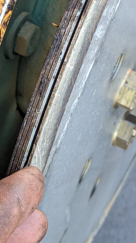
I just happened to be removing generators from one of my boats today. Here is the stacked disk flex plate. It's about 1/4 thick with 5 disks.

RE: Flexplate design: misalignment and fatigue

(OP)
Wow, very interesting. A laminated construction was not on my radar at all.

I took a look at that SAE paper. It was very general in nature - pretty much no numbers, but the conclusion was useful: shot-peening raised the strength enough to avoid the fatigue failures they were seeing.

Thanks again for the suggestions and information.

RE: Flexplate design: misalignment and fatigue

Question how do those 5 plates attach to the one towards the outside with the threaded holes? Nuts on the back side? Or vise versa.

Red Flag This Post

Please let us know here why this post is inappropriate. Reasons such as off-topic, duplicates, flames, illegal, vulgar, or students posting their homework.

Red Flag Submitted

Thank you for helping keep Eng-Tips Forums free from inappropriate posts.
The Eng-Tips staff will check this out and take appropriate action.

Reply To This Thread

Posting in the Eng-Tips forums is a member-only feature.

Click Here to join Eng-Tips and talk with other members! Already a Member? Login


News


Close Box

Join Eng-Tips® Today!

Join your peers on the Internet's largest technical engineering professional community.
It's easy to join and it's free.

Here's Why Members Love Eng-Tips Forums:

Register now while it's still free!

Already a member? Close this window and log in.

Join Us             Close