×
INTELLIGENT WORK FORUMS
FOR ENGINEERING PROFESSIONALS

Contact US

Log In

Come Join Us!

Are you an
Engineering professional?
Join Eng-Tips Forums!
  • Talk With Other Members
  • Be Notified Of Responses
    To Your Posts
  • Keyword Search
  • One-Click Access To Your
    Favorite Forums
  • Automated Signatures
    On Your Posts
  • Best Of All, It's Free!

*Eng-Tips's functionality depends on members receiving e-mail. By joining you are opting in to receive e-mail.

Posting Guidelines

Promoting, selling, recruiting, coursework and thesis posting is forbidden.

Students Click Here

Which constraints should I set to simulate stiffened panel under pure shear?

Which constraints should I set to simulate stiffened panel under pure shear?

Which constraints should I set to simulate stiffened panel under pure shear?

(OP)
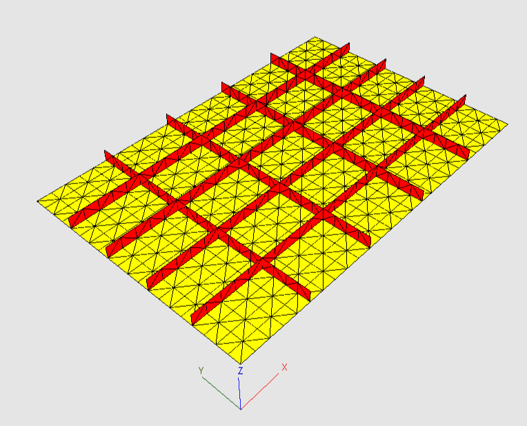
I have a stiffened panel that looks like this:


This panel is under shear:


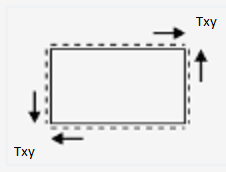
All sides of the panel are pinned. Txy - is distributed shear load.
Which constraints should I set to simulate stiffened panel under pure shear?

As for me I did this (but don't know is it good approach):
Constraints:
        Tx Ty Tz Rx Ry Rz
Left:   -  -  x  -  -  x
Right:  -  -  x  -  -  x
Top:    -  -  x  -  -  x
Bottom: -  -  x  -  -  x
A:      x  x  -  -  -  -
D:      -  x  -  -  -  -

Where: Tx, Ty, Tz - translational degrees of freedom
       Rx, Ry, Rz - rotational degrees of freedom
       '-' denotes free degree of freedom
       'x' denotes fixed degree of freedom
       A - left bottom node   //   B ---- C
       D - right bottom node  //   |      |
                              //   A ---- D

Then I set distributed load on each side in appropriate direction.
 
So which kind of constraints would you advice?

RE: Which constraints should I set to simulate stiffened panel under pure shear?

Generally those boundary conditions seem correct apart from unnecessary constraint Rz=0 for all edges.

If you are not sure about BCs, run a simple test analysis of a rectangular plate (without stiffeners) subjected to in-plane shear. Its results should show you whether the constraints are correct or not.

RE: Which constraints should I set to simulate stiffened panel under pure shear?

ok, you've constrained the plate for shear, now how are you going to load it ? Replace constraints on a long side and a short side with UDL. Well a "proper" UDL ... 1/2 the QUAD load at each node (so that the extreme end nodes see only 1/2 the typical node load, yes?)

another day in paradise, or is paradise one day closer ?

RE: Which constraints should I set to simulate stiffened panel under pure shear?

Some FEA programs offer special load called shell edge load and one of its types is shear. But of course it depends which software is used.

RE: Which constraints should I set to simulate stiffened panel under pure shear?

another thing ... are the stiffeners 1D elements (rods) or 2D elements (cap and web) ? what constraint for the non-shear_web node ? I'd suggest axial load.

another day in paradise, or is paradise one day closer ?

RE: Which constraints should I set to simulate stiffened panel under pure shear?

EP - do you want the edges to remain straight? Your bc’s will not enforce that.

Start with an unstiffened plate model and work out loads and bc’s to get a state of pure shear stress. Then move to the stiffened panel.

And remesh with quad elements. If you are using 4 noded tet elements the results will be rubbish (at best).

RE: Which constraints should I set to simulate stiffened panel under pure shear?

You can have a look here under the INDIVIDUAL DOCUMENTS section. For the Basic Manual, Page 7 discusses the boundary conditions and some specifics about it. The Validation Cases PDF shows that this approach is accurate for in-plane loading (Nxy loading).

https://www.structuralfea.com/PlateMesh/download.h...

Brian
www.espcomposites.com

RE: Which constraints should I set to simulate stiffened panel under pure shear?

yeah, but "straight" edges is like "fixed constraint" ... a theoretical "construct" rather than a true reality.

I agree with the approach of starting with a simpler model and loading, and get that right (or "right") and adding complication.
One thing to think about is "what's beyond the model?" is it a rigid body or a theoretically infinite shear panel ? Possibly model as a cylinder if infinite ? Possibly model as "super-element" and combine 9 (16?, 25 ??) pieces together to see what happens.

For edges, maybe add a beam with very low area but very high I

yeah, avoid TET4s like they were some "red-haired orphan". But meshing this with TETs would take a lot of elements ! (but so what if it takes 5 minutes to run ...)

another day in paradise, or is paradise one day closer ?

Red Flag This Post

Please let us know here why this post is inappropriate. Reasons such as off-topic, duplicates, flames, illegal, vulgar, or students posting their homework.

Red Flag Submitted

Thank you for helping keep Eng-Tips Forums free from inappropriate posts.
The Eng-Tips staff will check this out and take appropriate action.

Reply To This Thread

Posting in the Eng-Tips forums is a member-only feature.

Click Here to join Eng-Tips and talk with other members! Already a Member? Login


Resources

Low-Volume Rapid Injection Molding With 3D Printed Molds
Learn methods and guidelines for using stereolithography (SLA) 3D printed molds in the injection molding process to lower costs and lead time. Discover how this hybrid manufacturing process enables on-demand mold fabrication to quickly produce small batches of thermoplastic parts. Download Now
Design for Additive Manufacturing (DfAM)
Examine how the principles of DfAM upend many of the long-standing rules around manufacturability - allowing engineers and designers to place a part’s function at the center of their design considerations. Download Now
Taking Control of Engineering Documents
This ebook covers tips for creating and managing workflows, security best practices and protection of intellectual property, Cloud vs. on-premise software solutions, CAD file management, compliance, and more. Download Now

Close Box

Join Eng-Tips® Today!

Join your peers on the Internet's largest technical engineering professional community.
It's easy to join and it's free.

Here's Why Members Love Eng-Tips Forums:

Register now while it's still free!

Already a member? Close this window and log in.

Join Us             Close