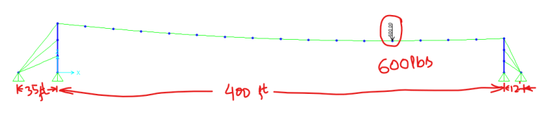
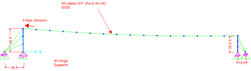
Assuming a 3/4" span wire (Single steel wire rope; no other cables), 90mph wind load, 600 lb point load w/ 20 sq. ft. projected area, and stiff (nearly rigid) supports, here are the numbers I get from my analysis spreadsheet:
At 5% sag:
Wire tension - 5.7 kips
Maximum sag - 25'
At 3% sag:
Wire Tension - 9.4 kips
Maximum sag - 17'
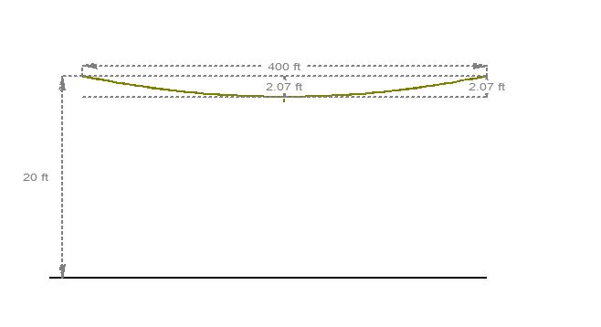
At 2% sag:
Wire tension - 14.0 kips
Maximum sag - 13.5'
1/2" span wire (other loading same) at 5% sag:
Wire tension - 5.1 kips
Rod Smith, P.E., The artist formerly known as HotRod10
![[lol]](/data/assets/smilies/lol.gif "[lol] [lol]")