×
INTELLIGENT WORK FORUMS
FOR ENGINEERING PROFESSIONALS

Contact US

Log In

Come Join Us!

Are you an
Engineering professional?
Join Eng-Tips Forums!
  • Talk With Other Members
  • Be Notified Of Responses
    To Your Posts
  • Keyword Search
  • One-Click Access To Your
    Favorite Forums
  • Automated Signatures
    On Your Posts
  • Best Of All, It's Free!

*Eng-Tips's functionality depends on members receiving e-mail. By joining you are opting in to receive e-mail.

Posting Guidelines

Promoting, selling, recruiting, coursework and thesis posting is forbidden.

Students Click Here

Heat Transfer through lenses

Heat Transfer through lenses

Heat Transfer through lenses

(OP)
Hi to everybody.
I am in a bit of a problem for calculating the various convective coefficients for the heat transfer through two lenses made of sapphire.
I have to create a window that will let a thermal camera see into the medium pressure stage (and later i will do the same study for the high pressure stage) of a Steam Turbine. The window will be created in a sort of hollow point of the outer casing, so I can conclude, or approximate, that the steam that pass there is immobile. So near the first lens the velocity of the steam is zero.

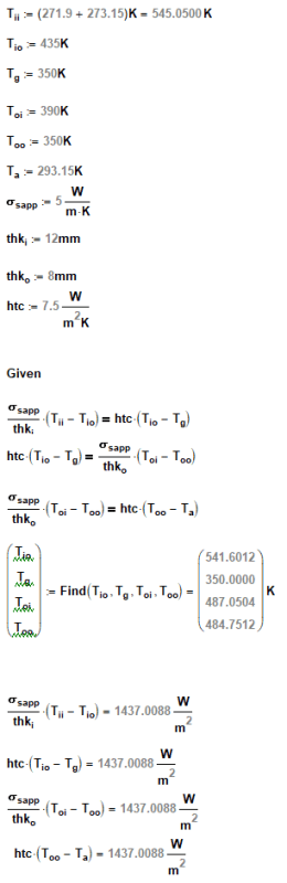
Now, i attach an image for better undestanding.
Data is:

lenses made of Sapphire (Al2O3) of Diameter 64mm.
The lenses are clamped, so the usable diameter is 54mm
T1=271,9 °C p1=5,752 bara
x1=12mm

cavity filled with air at p=pamb, later filled with nitrogen at p=pamb
x2=8mm
T2=20°C, p2=pamb

Now, as first approximation(after the immobile steam near the first lens) I can resolve my problem as a 1 Dimension Steady State (in the end I will use the thermal camera always in steady state).
How do i calculate the three convective coefficients?

Thanks in advance

RE: Heat Transfer through lenses

Are you trying to calculate the heat loss through the window or trying to calculate an offset to apply to readings from your thermal camera?

If you are trying to calculate the heat loss, assuming your turbine body is metal, I would expect the lens and the temperature of the nitrogen in the gap to basically be the same temperature as the housing wall at that point. So outer lens temp is same as outer wall, inner lens temp same as inner wall, etc.. Since there is nothing circulating the nitrogen in the gap conduction will win out.

If you are trying to calculate an offset for you thermal camera you will need to look at the transmission % of the sapphire over the wavelengths that your camera is sensitive to. Any coatings could have a very big effect too. For example, if we assume you are using a MWIR camera and sapphire transmits roughly 80% between 3-5um wavelengths you would be looking at only 64% of those wavelengths getting through your two lenses. Of course, if you are trying to measure absolute temperatures of components using a thermal camera the emissivity of the materials will have an even larger effect on the temperature values you read.

RE: Heat Transfer through lenses

Sorry, but that first sentence really grated on my ears. Convection, per se, does not directly apply to the overall heat transfer, since there is no fluid flow in the lenses. It's convection to the surface, conduction through the lens and housing, convection in the gap, conduction through the second lens, and convection after that. Radiation does occur through the entire path.

x1 and x2 are thicknesses? What is the gap spacing?

What exactly are you trying to see? Infrared sensors are not particularly good at seeing through steam.

TTFN (ta ta for now)
I can do absolutely anything. I'm an expert! https://www.youtube.com/watch?v=BKorP55Aqvg
FAQ731-376: Eng-Tips.com Forum Policies forum1529: Translation Assistance for Engineers Entire Forum list http://www.eng-tips.com/forumlist.cfm

RE: Heat Transfer through lenses

(OP)
Hi, thanks for your kind reply.
First of all,
@IRstuff:
I am sorry, but i didn't mean i thought there would have been only convection, it would be nonsense.
x1 and x2 are the thickness of the two lenses. The thermal conductivity of sapphire is 40 W/mK at 27°C and 4 W/mK at 1227°C(it is not linear, but I still have to find a table containing various Thermal conductivity coefficients at various temperatures).
I am triyng to see the metal surface temperature of the rotor that is visible from this window.

@hendersc:
I still don't have the cavity thickness between the 2 lenses because I will have to implement it. I can prematurely say that it is 10mm.
Speaking for the gap made of air, I was not sure that I could say that it was only conductive tranfer in the gap, So I went and searched the Italian normes(I'm from Italy) to find the cavity resistance. I found some normes for buildings(so for thicker gaps, at least 5mm) saying that I can consider it only conductive transfer IF the cavity gap is 10% or less than one of the two walls surrounding it, so the gap should be less than 0.8mm. Unfortunately, even if I wanted to use it like that, there was only a Resistance for a gap of 5mm.
I already did some preliminar calculation with H1=510 W/m2K (really high,it was from a study on a combustor, so it is useless), H2=10W/m2K, Hi=15 W/m2K (the internal one was totally random, but I had to start from somewhere) and it turns out that the second lens was at 126°C, and the first at 269°C.

I will use all of this to calculate the thermal and mechanical stresses of the 2 lenses, but to try and be as precise as possible I have to find a way to calculate the convective coefficients (and find a table for the thermal conductivity of sapphire, but that should not be a problem),

How do I calculate the convective coefficents of the various stages?

RE: Heat Transfer through lenses

The building references you are looking at would be using wood, concrete, sheet rock, etc that are all thermal insulators vs the metal of your turbine housing. They are also likely assuming that the gap extends across the whole surface, not just a very small window. Take these references with a big grain of salt

At the very least, the outer edges of your sapphire windows that are in contact(in some way) with the metal housing will be the same temperature as the metal housing. You could look at this from a worst case perspective instead of trying to get exact values. The worst case (I assume) would be for the sapphire to be at the higher housing temperature.

It sounds like you are trying to neglect any heat transfer through the housing to the lens or through the housing to the air gaps which I think will give you much lower temperature values. I would suggest throwing this into a CFD software so you don't need to neglect one form or another of heat transfer.

RE: Heat Transfer through lenses

I'm getting really confused here. It seems to me that you are asking a different question:
> Can the imager see through the window system? which is a different question than your heat transfer question

The answer to that question depends on the transmission of the image photons through the steam. Ignoring the steam for the moment, if the transmission of the two "lenses" which I assume are actually flat panes of sapphire, is tolerably high, even 25% transmission might be sufficient, then you can "see" through the window.

The steam is a bigger problem, since it not only obscures by absorbing photons, it's the hottest material in the system and emits a bunch of photons on its own that can mask the contrast of features in the rotors that you are trying to image.

TTFN (ta ta for now)
I can do absolutely anything. I'm an expert! https://www.youtube.com/watch?v=BKorP55Aqvg
FAQ731-376: Eng-Tips.com Forum Policies forum1529: Translation Assistance for Engineers Entire Forum list http://www.eng-tips.com/forumlist.cfm

RE: Heat Transfer through lenses

(OP)
No, I am not interested on the thermal camera, if it will work and how; i am only asking How can i Calculate the 3 convective coefficients.
How do i calculate them?
I found out that the property of steam at the exit(so near that window)
flow=13,45 kg/sec
entalphy=3004,3 kJ/kg

RE: Heat Transfer through lenses

You need to know the thermodynamic properties of the gasses involved (this is easy, look them up)

And then you need to know their velocities relative to the surfaces. If your lenses are very small (which I assume they are) then the convection between them will be very minimal, because of extremely small velocities.

What you really need is the velocity of the steam against the innermost lens surface- your assumption that the velocity on the inside of the lens is zero is almost certainly incorrect.

RE: Heat Transfer through lenses

A drawing of the steam flow w.r.t. the window would certainly help

What surface temperature is the housing at? To the first order, the outer window temperature will be that of the housing around it

TTFN (ta ta for now)
I can do absolutely anything. I'm an expert! https://www.youtube.com/watch?v=BKorP55Aqvg
FAQ731-376: Eng-Tips.com Forum Policies forum1529: Translation Assistance for Engineers Entire Forum list http://www.eng-tips.com/forumlist.cfm

RE: Heat Transfer through lenses

(OP)
yeah, i'll go and see if i can find some reliable way to calculate he speed near that wall, but i already know it will be impossible. I probably will use the flow at the exit of the casing (i have to find the diameter if the exit, don't know where to look).

Red Flag This Post

Please let us know here why this post is inappropriate. Reasons such as off-topic, duplicates, flames, illegal, vulgar, or students posting their homework.

Red Flag Submitted

Thank you for helping keep Eng-Tips Forums free from inappropriate posts.
The Eng-Tips staff will check this out and take appropriate action.

Reply To This Thread

Posting in the Eng-Tips forums is a member-only feature.

Click Here to join Eng-Tips and talk with other members! Already a Member? Login


Resources

Low-Volume Rapid Injection Molding With 3D Printed Molds
Learn methods and guidelines for using stereolithography (SLA) 3D printed molds in the injection molding process to lower costs and lead time. Discover how this hybrid manufacturing process enables on-demand mold fabrication to quickly produce small batches of thermoplastic parts. Download Now
Design for Additive Manufacturing (DfAM)
Examine how the principles of DfAM upend many of the long-standing rules around manufacturability - allowing engineers and designers to place a part’s function at the center of their design considerations. Download Now
Taking Control of Engineering Documents
This ebook covers tips for creating and managing workflows, security best practices and protection of intellectual property, Cloud vs. on-premise software solutions, CAD file management, compliance, and more. Download Now

Close Box

Join Eng-Tips® Today!

Join your peers on the Internet's largest technical engineering professional community.
It's easy to join and it's free.

Here's Why Members Love Eng-Tips Forums:

Register now while it's still free!

Already a member? Close this window and log in.

Join Us             Close