×
INTELLIGENT WORK FORUMS
FOR ENGINEERING PROFESSIONALS

Log In

Come Join Us!

Are you an
Engineering professional?
Join Eng-Tips Forums!
  • Talk With Other Members
  • Be Notified Of Responses
    To Your Posts
  • Keyword Search
  • One-Click Access To Your
    Favorite Forums
  • Automated Signatures
    On Your Posts
  • Best Of All, It's Free!

*Eng-Tips's functionality depends on members receiving e-mail. By joining you are opting in to receive e-mail.

Posting Guidelines

Promoting, selling, recruiting, coursework and thesis posting is forbidden.

Students Click Here

Simplify 2D/Shell Mesh

Simplify 2D/Shell Mesh

Simplify 2D/Shell Mesh

(OP)
All,

I was looking at some techniques to simplify Shell mesh structures.

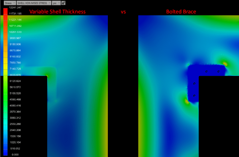
As an example, I have a door edge with a bolted brace as shown. The brace is 0.25" while the steel structure is 10 gauge steel.
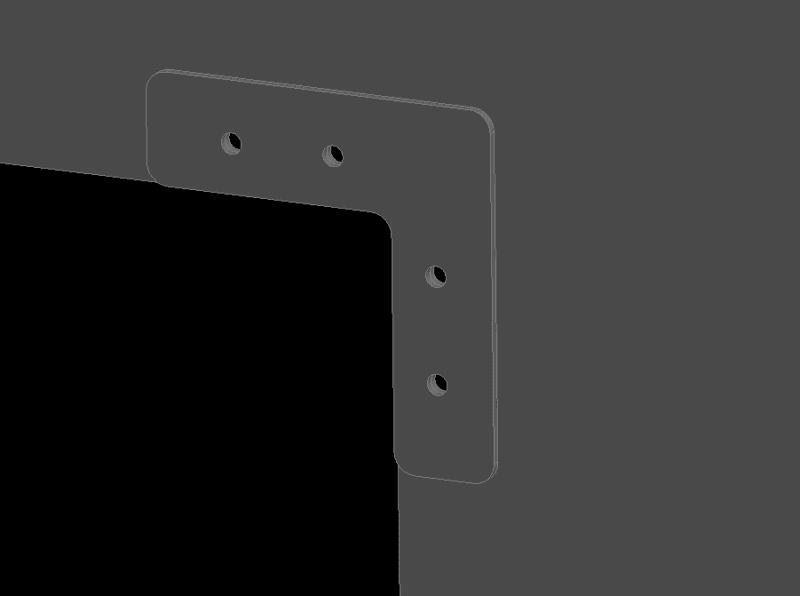


Can this be simplified to a 2D mesh with two separate mid surfaces
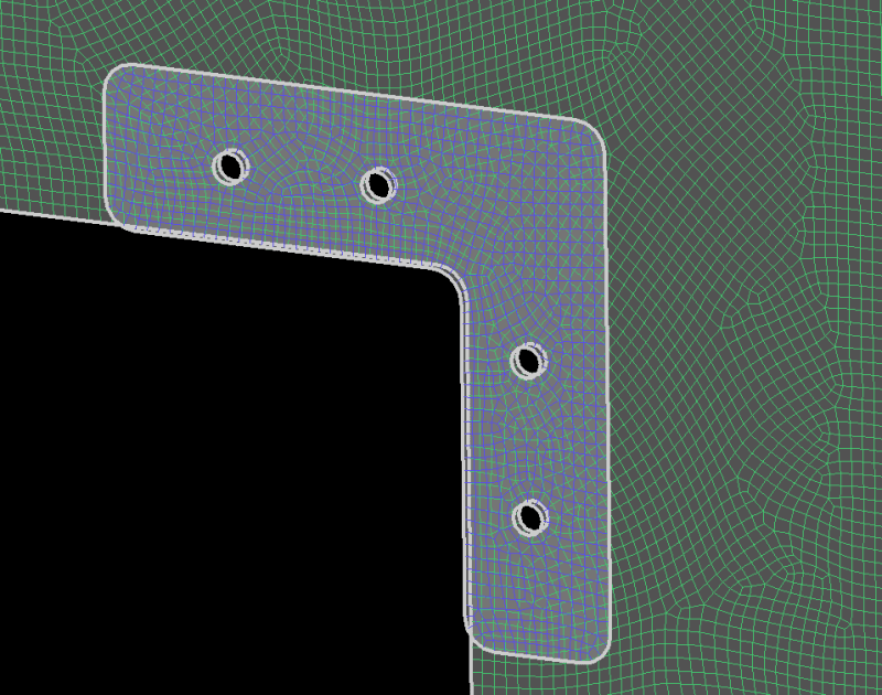


OR

A single shell mesh with split surface and different plate thickness?
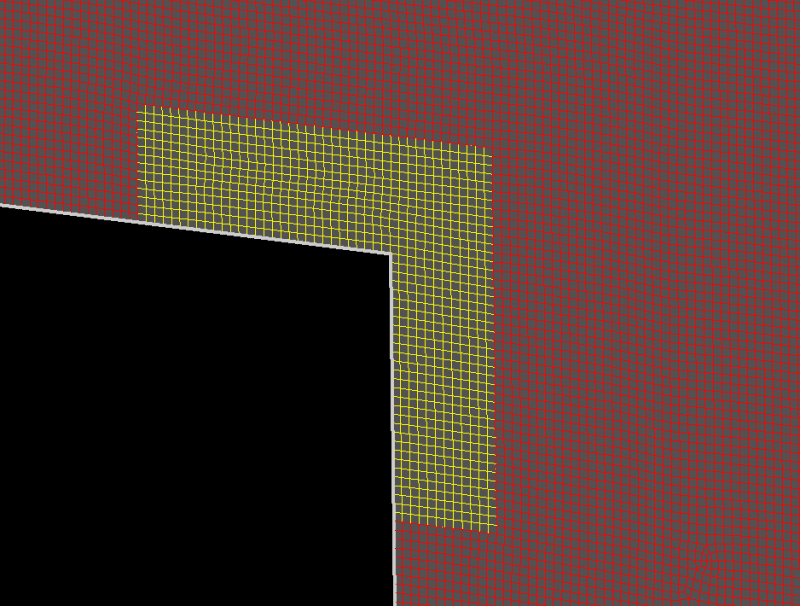


Thank you!
Replies continue below

Recommended for you

RE: Simplify 2D/Shell Mesh

The second approach (variable shell thickness) seems like a good idea in this case.

RE: Simplify 2D/Shell Mesh

(OP)
Thanks @FEA way, I'm not really concerned about the fasteners, just transfer of loads for a part that is not expected to fail.

RE: Simplify 2D/Shell Mesh

I would rather the first one ... the bolted plate is not going to be as effective as a thickness pad-up. It's not the fastener loads that are important but the effective material at the corner radius.

looks like we're going to have to make a deposit at the element bank ... someone's made a large withdrawal ...

another day in paradise, or is paradise one day closer ?

RE: Simplify 2D/Shell Mesh

(OP)
@rb1957,

Affirmative. However, some of the consultants work involves extensive use of method 2.

RE: Simplify 2D/Shell Mesh

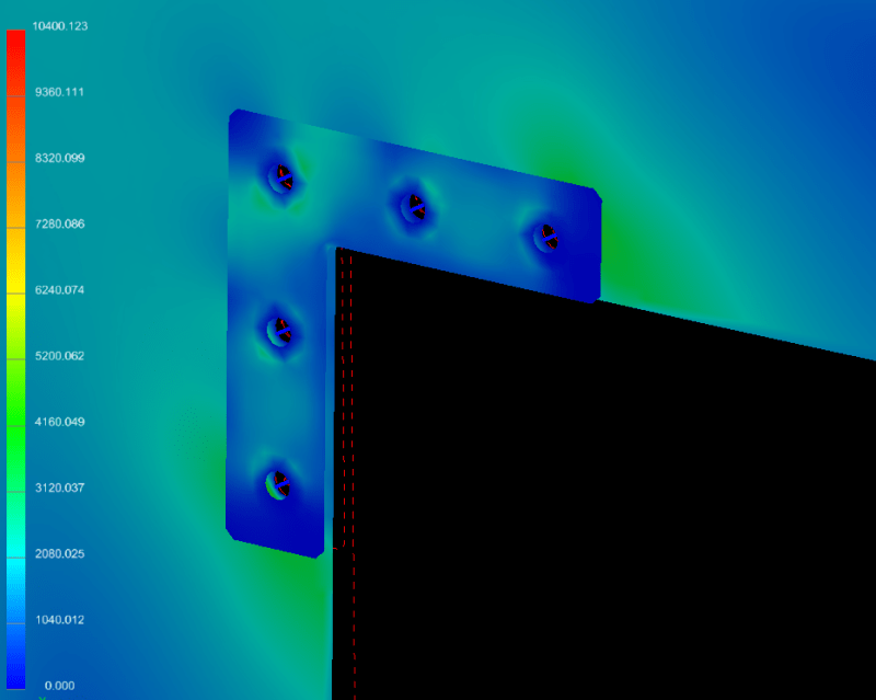
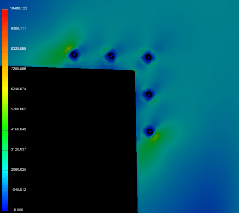
I have a feeling that is showing exactly what I mean. When the bolted on dblr is merged with the panel (LH view) the stresses are lower, the strap more effective.

on the RH view the low stresses in the dblr are hiding the higher stresses in the panel (under the strap) ... not sure why there's a local spike and the corner of the strap (which should be unconnected to the plate).

another day in paradise, or is paradise one day closer ?

RE: Simplify 2D/Shell Mesh

Both approaches are bad.
Do not model the fastener holes. Too complicated and just gives rubbish stress peaks at the holes.
Modelling as smeared plates ignores the fasteners flexibility and over predicts load into the doubler.
Best is to create two separate layers of shell elements without any holes, then connect with fastener elements at the fastener locations.

RE: Simplify 2D/Shell Mesh

I would use option 1

  • Connect the mid-surfaces with rigid spiders
  • Ignore stress risers at the spiders
  • Check the fasteners by hand
SW how would you propose to connect the plates if you didn’t include the holes?


“Any idiot can build a bridge that stands, but it takes an engineer to build a bridge that barely stands.”

RE: Simplify 2D/Shell Mesh

SW would probably use CBUSH spring elements, or rigid links (common nodes).

I agree modelling the holes is "overkill" but in this case consistent with the mesh density shown (which I feel is overkill). But modelling holes is easy these days.

The depth of analysis depends on your focus. If you're analyzing the wall or the building then you're going to spend less time and attention on this detail, and I might not model the dblr at all, and maybe include it in hand calcs if I needed to. If you're analyzing this strap then you go into this type of detail modelling and determining fastener loads would be important to you.

another day in paradise, or is paradise one day closer ?

RE: Simplify 2D/Shell Mesh

(OP)
With CBUSH elements for bolts/pretension and appropriate contact, I think I got the correct stress response.

RE: Simplify 2D/Shell Mesh

don't understand the small spike at the corners of the strap (in the LH pic ?

The LH pic is a pad up (merge the brkt into the plate) ? which would explain the spikes.

The RH pic shows the strap on top of the plate ? view the plate under the strap (the plate stresses will be higher).

another day in paradise, or is paradise one day closer ?

RE: Simplify 2D/Shell Mesh

(OP)
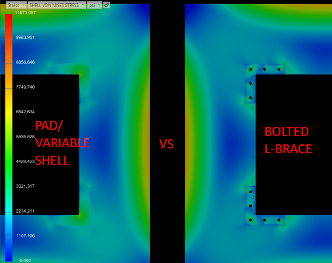
rb1957, are you saying that the plate stresses will be higher in spite of the L-Brace being thicker than the structure it holds?

RE: Simplify 2D/Shell Mesh

I'm saying the plate stresses under the L-brace (attached by fasteners) will be higher than the L-brace stresses.

This is a picture of the plate and L-brace together, yes?

try plotting just the plate elements.

another day in paradise, or is paradise one day closer ?

RE: Simplify 2D/Shell Mesh

(OP)
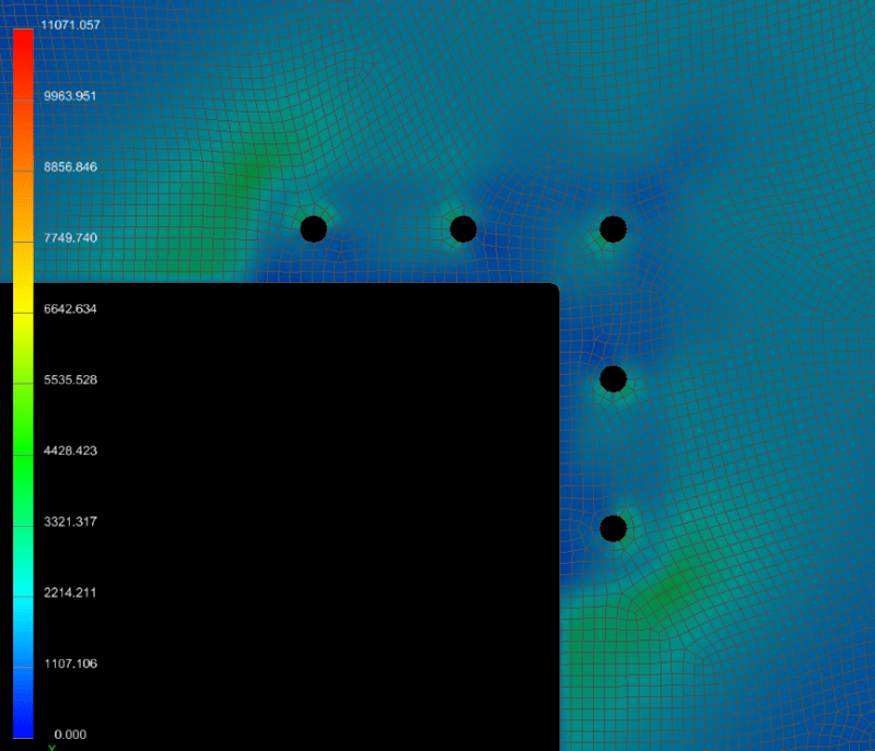
The rear plate, 0.179" thk.

RE: Simplify 2D/Shell Mesh

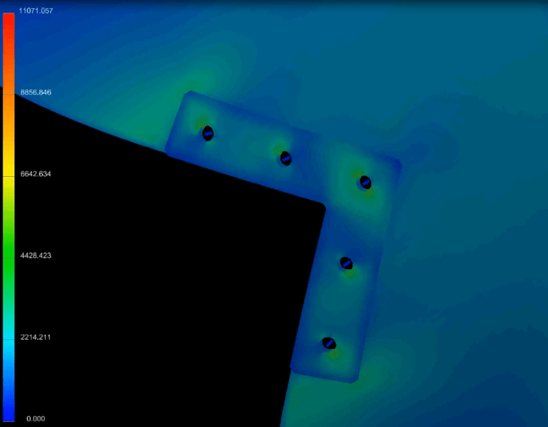
something seems "odd" ...

it seems to understand the perimeter of the L-strap, much more than I'd've thought ?

it seem "odd" that there is a very mild stress peak near the fasteners, and this is wiped out under the strap, and then another stress peak in the plate ?

I'd've expected a stress peak from the fasteners radiating out from under the plate,

I would not have expected a stress peak in the plate at the perimeter of the L-strap,

I would have expected more of a stress peak at the corner, with such a tight radius.

another day in paradise, or is paradise one day closer ?

RE: Simplify 2D/Shell Mesh

(OP)
I reset the analysis.

L-brace = 0.25", Plate = 0.179"

Pressure on plate rear = 1 psi (rectangular air plenum)

Bolts = A307,GradeA,3/8"-16, with 2092 lb preload, modeled as CBUSH

Contact = separation, contact element activation distance = 0.275"

Brace Front:


Plate Rear:

RE: Simplify 2D/Shell Mesh

(OP)
The idea of the exercise was to simplify the analysis, however, that does not seem to be working out. Is there no way out?

RE: Simplify 2D/Shell Mesh

ok, I didn't realise out-of-plane loading, that explains the foot print of the L-brace.

Still surprisingly small stress peak in the corner.

I wonder if this L-brace is actually helping ?

This is just a flat plate with pressure applied ? I wonder why no stiffening flange around the cut-out ?

"is there no way out ?" ... if you want the right answer, or "truth", then no; truth requires the most complicated analysis possible. If you want "near enough" then I'd suggest ignoring the L-brace (presumably conservative), there may be other practice reasons for adding it, not related to reducing stress level.

another day in paradise, or is paradise one day closer ?

RE: Simplify 2D/Shell Mesh

(OP)
@rb1957, I appreciate the help. Early FEA days are overwhelming and tumultuous.

RE: Simplify 2D/Shell Mesh

start with simple models, that you can hand calc. GL

another day in paradise, or is paradise one day closer ?

Red Flag This Post

Please let us know here why this post is inappropriate. Reasons such as off-topic, duplicates, flames, illegal, vulgar, or students posting their homework.

Red Flag Submitted

Thank you for helping keep Eng-Tips Forums free from inappropriate posts.
The Eng-Tips staff will check this out and take appropriate action.

Reply To This Thread

Posting in the Eng-Tips forums is a member-only feature.

Click Here to join Eng-Tips and talk with other members! Already a Member? Login


News


Close Box

Join Eng-Tips® Today!

Join your peers on the Internet's largest technical engineering professional community.
It's easy to join and it's free.

Here's Why Members Love Eng-Tips Forums:

Register now while it's still free!

Already a member? Close this window and log in.

Join Us             Close