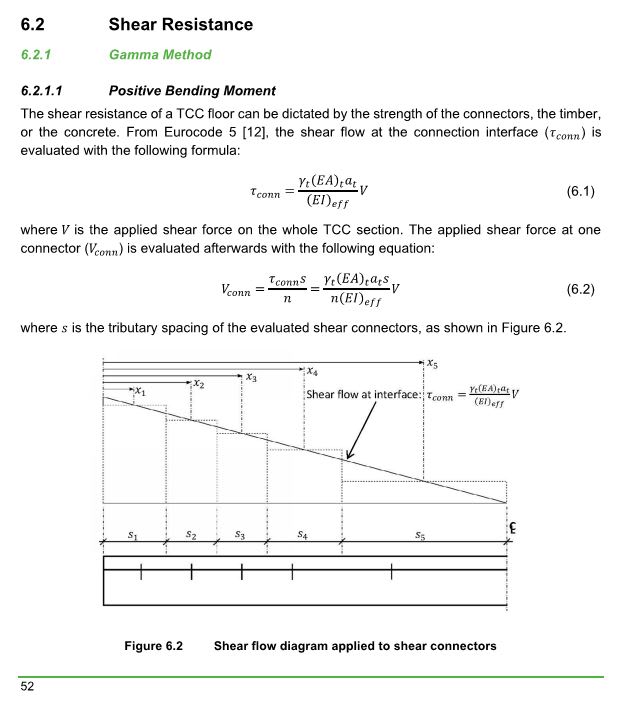
shear capacity of composite ceiling
(OP)
Timber beams 180 x 240 (no spacing between), on top plywood and RC slab (70 mm thic). Connection between slab and timber are nails as shown bellow.
How do I calculate shear capacity per 1,00 m (kN/m) for such composite ceiling?

How do I calculate shear capacity per 1,00 m (kN/m) for such composite ceiling?


RE: shear capacity of composite ceiling
Although are you potentially meaning to calculate the interface shear between concrete and wood to achieve composite action, and maybe you are not referring to the vertical shear capacity?
Also for the interface shear, your nails would have a tendency to pull out if angled as shown? If you consider the interface between the wood and slab moving relative to one another as the system is loaded, the slab wants to slide [towards the ends of the wood beam] relative to the wood beam. This would have the effect of withdrawing the nails wouldn't it as the interface shear developed (might be designed for this limit state/effect though?). Nails are obviously quite poor in withdrawal compared to loading them in shear. Maybe they are screws though?
My first thoughts are that I'd expect them to be at right angles to the beam surface, least thats what I've seen on previous projects where people have tried to develop some composite action between wood and concrete slabs.
RE: shear capacity of composite ceiling
I read the thread a few times.. Is the question spacing of nails or the shear capacity of the beam for 1,0 m width ?
IMO, you may calculate both using the transformed section. Typical values for timber Et=9000 mPa Ec= 25000 MPa. and the allowable horizontal shear stress of timber ( around 90 psi) should control the capacity of the composite beam.
Pls provide more info. to get better responds.. Is this a real problem? What is dictating the wooden beams to behave together except the 20 mm thk plywood ?
IMO, if i were in your shoes, i would prefer the floating RC slab. ( 7 mm rc screed + 20 mm hard rockwool + 260 mm timber).
RE: shear capacity of composite ceiling
It's an existing thing.
I'd like to calculate vertical shear capacity (kN/m). The most simple way is to consider timber beams only, but I'd like to calculate it for composite section.
If I use transformed section method I should consider connections - screws in (slippage)
RE: shear capacity of composite ceiling
As I said, I’d still be taking timber only for vertical shear.
Is this a common form of construction where you are? I’ve never come across it before but it looks interesting - more something I’d love to have done as a thesis rather than do in the real world!
RE: shear capacity of composite ceiling
If old / existing timber beams are in good/acceptable condition we make composite ceiling by putting screws (based on thicknes, material, span and loads for horizontal shear). And then pour concrete slab or screed on top with reinforc. mesh for crack control. Slab is also anchored in bearing walls so it connects bearing walls (acts as diaphragm). It's not what I would do for new structures but it's a common thing for old buildings that are not allowed to be demolished.
Can you elaborate?
RE: shear capacity of composite ceiling
If the concrete shrinks and cracks, then presumably at that particular point it has zero shear capacity and you’re left with the shear capacity of the timber only in any event?
Just ignore me if I’m missing something - as I said, I’ve just never seen this before.
RE: shear capacity of composite ceiling
If I understand your reinforcing process correctly this is akin to a composite steel beam where the concrete is used for it's compression block in flexural resistance but the steel beam is assumed to resist the shear.
The method seems a bit counter intuitive to me as the additional dead load from the concrete would seem to be working against you here.
My Personal Open Source Structural Applications:
https://github.com/buddyd16/Structural-Engineering
Open Source Structural GitHub Group:
https://github.com/open-struct-engineer
RE: shear capacity of composite ceiling
Pardon my ignorance, but for new builds, why would you choose a concrete topped mass timber floor? I’d have thought the dead weight of concrete eventually reaches a point of diminishing return when compared to a mass timber floor of equivalent depth?
RE: shear capacity of composite ceiling
I'm not an expert on this but I believe that the concrete topping is included primarily to create a finished surface that feels "institutional".
RE: shear capacity of composite ceiling
They seem to be saying that the vertical shear that can be carried is either governed by the shear capacity of the interface, or the timber beam alone. So as people have stated, only the bare timber beam should be considered in the normal sense for resisting beam shear, but also just need to confirm you have sufficient shear connection to develop any composite moment capacity required (and the corresponding interface shear which is proportional to the beam shear).
RE: shear capacity of composite ceiling
The shear resistance of the whole TCC floor is reached when the first component reaches its
strength. Thus, the following equation gives the shear resistance of the whole TCC floors (𝑉𝑟):
𝑉𝑟 = min(𝑉𝑟,𝛾,𝑐𝑜𝑛𝑛;𝑉𝑟,𝛾,𝑡; 𝑉𝑟,𝛾,𝑐) (6.16)
In negative bending region,
In negative bending moment, the (𝐸𝐼)𝑒𝑓𝑓 is calculated according to the equation presented in
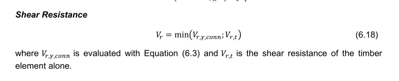
Section 2.3.5.2. A conservative approach to evaluate the shear resistance of the composite beam
is to neglect the shear force taken by the concrete slab. Consequently, the shear resistance is
evaluated with the following equation:
𝑉𝑟 = min(𝑉𝑟,𝛾,𝑐𝑜𝑛𝑛;𝑉𝑟,𝑡) (6.18)
RE: shear capacity of composite ceiling
It seems to me that they're only saying that for negative moment regions, and for obvious reasons. It appears to me that, for positive moment regions, they are allowing composite behavior to improve shear capacity. I've only really skimmed this document so far, however, so it's entirely possible that I've missed something.
From a mechanics perspective, we know that horizontal shear and vertical shear are complimentary. In that sense, having the gain in horizontals shear pretty much guarantees also having it in vertical shear. That said, a little extra conservatism in the vertical shear is understandable if that's the story that we're telling.
RE: shear capacity of composite ceiling
To answer OP’s question, I’m still inclined to take the shear capacity of the timber only.
RE: shear capacity of composite ceiling
1) Nothing so long as one of the following is true:
a) the shrinkage crack is small enough to not compromise aggregate interlock shear capacity and/or
b) the governing shear failure mode occurs on a diagonal plane rather than a vertical one.
2) In my mind, with proper connectors, this is fundamentally similar to these two situations where we normally do allow for shear enhancement as a result of toppings that will have restrained shrinkage cracking:
a) composite concrete slabs cast over metal deck and;
b) composite topping slabs cast over hollow core plank.
RE: shear capacity of composite ceiling
But I'm having trouble determining for positive bending what Vr,t and Vr,c are in equations 6.14 and 6.15, as cannot find it in the guide proper. In the example I think they work through it, but just stated the value for Vr,t (any chance you could confirm thats just the stock standard normal shear capacity for timber.
Being familiar with Canadian ways, are they the individual shear capacities of timber and concrete determined normally on their own in isolation (from appropriate codes, the only equation given in the example is for the Vr,c concrete shear capacity and not sure if that is a capacity just for this purpose or from concrete code or something?)
I'd need to work through the rest of eqn 6.14 and 6.15 to see how much the multiplier might be over any above the bare timber or concrete shear capacities. In the example, the composite shear capacity comes out lower than the bare timber, as it was limited by the concrete shear capacity. I guess it's analagous to a flitch beam, in that you're after the composite capacity when one of the materials/components reaches it's limit.
Hopefully the OP can post back his findings if using this.
RE: shear capacity of composite ceiling
As I said, this is a completely new one for me!
RE: shear capacity of composite ceiling
In the example the concrete governed the shear capacity.
RE: shear capacity of composite ceiling
In my opinion, OP still won't be able to use this methodology for lack of solid testing & recommendation's for the fasteners he's got. This stuff is fun to kick around, and I try to help where I can, but I still suspect that the path forward for OP will be timber shear capacity alone.
I'm afraid that I won't be able dive any deeper on this until the weekend, and may not even then if some of the bicycle parts that I have on order show up as planned. When I do a quick scan of the relevant equations, however, they strike me as follows:
1) Stresses calculated based on some manner of partially composite sections.
2) Individual material stresses from [1] compared to conventional limits for those materials.
The equations have that "flavor", you know?
I hear it. If I had to reinvent all of structural design myself from scratch, what I'd come with would be so ridiculously conservative that nothing would ever get built. I still sometimes shake my head that we happily assume that beam shear cracks will happen across stirrups rather than between them. Let's hear it for testing and collective experience!!
RE: shear capacity of composite ceiling
EDIT - not sure how I missed those 2 eqns, but good to know they are stock standard, as helps with possibly applying logic to other regions.
RE: shear capacity of composite ceiling
I believe in the example its a solid plank type CLT floor (184mm x 1000mm wide considered), they are simply working out the capacities based on a per meter width, which is where the b_c of 1000mm comes from. Review the pictures of the arrangement in the start of the example.