Continue to Site

Eng-Tips is the largest engineering community on the Internet

Intelligent Work Forums for Engineering Professionals

  • Congratulations waross on being selected by the Eng-Tips community for having the most helpful posts in the forums last week. Way to Go!

Torsion at bean with pinned ends 1

Status
Not open for further replies.

BAGW

Structural
Jul 15, 2015
392
Hi,

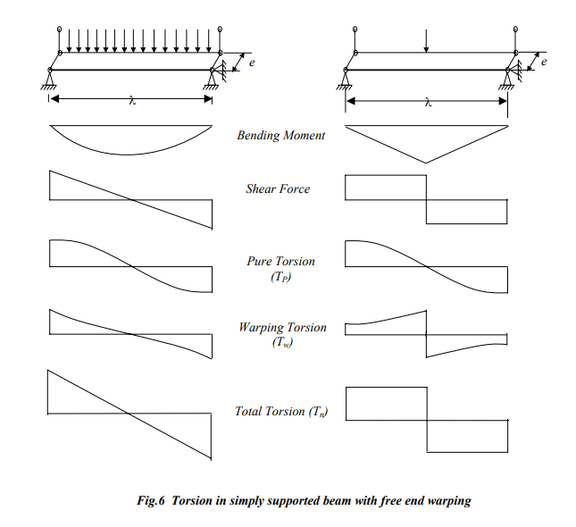
I am confused about concept of torsion in beams with pin ends. When the beams are attached with just a shear connection (pinned)how can the beam resist torsion? Wont the beam be unstable under torsion load? So what scenario does the AISC design guide case 3 refer to?

Thanks
 
Replies continue below

Recommended for you

You are correct. A beam with pinned ends cannot resist torsion. If it needs to resist torsion, some redesign is required.
 
Can you provide a sketch of the joint with direction of torsion indicated? Also, I would correct the typo in the subject - "bean".
 
I am confused too :) Link

image_kqmjwa.png
 
Exactly wrt the fig r13 has posted. Is the beam pinned for bending and fixed for torsion?

I am looking at case 3 in AISC dg which is similar to what r13 has posted
 
Does not matter, because torsion is a shear-centric phenomenon. Note that on diagram above, the shape of total torsion diagram is identical to the shear diagram regardless the type of edge support. When you have a torsion on bolted connection, wouldn't you expect the torsion is resolved into a couple separated by the bolt distance?
 
But isn’t that capacity very small? There will be bending on web
 
Huh? I'm confused at the responses here.

BAGW said:
When the beams are attached with just a shear connection (pinned)how can the beam resist torsion?

MIStructE_IRE said:
It can’t. It just flips over, end of.
Huh? If a pin or a shear plate doesn't provide any torsional resistance why aren't beams flipping over all the time. Where is the buckling restraint coming from in a single beam?

A 'pinned' connection or a 'shear' connection on a beam typically can resist torsion.

To be clearer we need to be specific about the degrees of freedom on the connection. A typical and a literally pin connect is translationally fixed in X,Y,Z. It is rotationally fixed in Z and free to rotate about X. Where X is the axis axis cutting horizontally through the beam, Y is vertical through the beam and Z is only the length of the beam. (I skipped rotational restraint about Y as it is mostly not relevant for a beam.)

Under the above definition being rotationally fixed about Z the connection provides torsional resistance. This applies to a literal pin connection as well as representative pin connection like shear plates and clip angles.

BAGW said:
Is the beam pinned for bending and fixed for torsion?

But isn’t that capacity very small? There will be bending on web
Yes. That is pretty much the definition of a literal pin and typical shear connection. If you want freedom to rotate in all directions then you likely want pins and a swivel or a ball and socket connection.

BAGW said:
But isn’t that capacity very small? There will be bending on web
Yes the torsion capacity is small but that doesn't mean it isn't a fixed torsion connection. Connection capacity is different to the connection's degrees of freedom.

You question sounds like it is an academic problem not a real world problem. In the real world you generally try to avoid torsion on members.
 
Yes, loosely designed pinned end is less capable of resist torsion. For small (compatibility) torsion, it is usually ignored. But, you need to design for the equilibrium torsion, if present, just as in rigid connection, or change the support type and/or modify the connection detail.
 
A teeter totter (or seesaw) is a good example of a pin which permits rotation about one axis only. It does not permit rotation about the other two. It wouldn't be much fun if it did.

BA
 
But isn’t that capacity very small? There will be bending on web

Practically speaking, there cannot be torsion transfer at the end of a wide flange beam without some sort of flange restraint because the web goes into bending.....and it cannot take it.

See this thread:
As far as the fixity goes....you are really (practically) somewhere in between fully fixed and fully pinned. (Like most beams.) What I have done is consider both types for max. stresses and rotations.....and provide for a load path to transfer the torque.
 
One of the issues that we have in communicating about this issue is a language issue.

What does the term "pinned" mean?

When said by itself, it usually means a connection that resists no bending moment. It's kinda undetermined if it resists torsion or not.

Said a different way, all REAL life pinned connections resist some moment, and some torsion. The amount is the question a shear plate vs a Double angle hear connection can be very different (at least as far as torsion resistance goes).

The AISC design guide on torsion using the term "torsional pin" connection to refer to a connection that resists torsional moment, but does not restrain torsional warping.

I'm guessing, the OP got confused when reading about a "torsional pin", not understanding the difference between torsion and torsional warping.
 
There are many types of pin. Some are shown below. When a pin is used at the end of a beam, free rotation is permitted about the pin. That is all it means, nothing more.

If the pin is parallel to the beam, torsion is prevented. If it is placed normal to the beam, the bending moment about the pin is zero.

image_ys2oiv.png
image_qsecgx.png
image_rqtlnf.png


BA
 
If you have equilibrium torsion, there are two ways to solve the problem:

1) Eliminate the torsion at the location it acts.
2) Design the members and connection to accommodate the torsional effects.

Anybody has suggestion to add to the actions above?
 
If I add a beam perpendicular to the beam subjected to torsion, how do I check if the connection is ok? See the attached image. If the beams are attached using double angle connection, how do I transfer the force to the double angles? Will there still be bending in web while transferring forces? One way is to add a full depth stiffener.

Document1_wfijjb.jpg
 
Josh is quite correct that it boils down to warping restraint. Obviously, even with some types of moment connections, you aren't completely restraining warping. (Ergo my comments before.)

[blue](r13)[/blue]

If you have equilibrium torsion, there are two ways to solve the problem:

1) Eliminate the torsion at the location it acts.
2) Design the members and connection to accommodate the torsional effects.

Anybody has suggestion to add to the actions above?

One thing I have done (and I talk about it in the thread I linked to) is to have beams (say in the case of a torque acting on a girder) framing into the torqued girder (on each side of the torque) and take it out that way. (Which you can do even with a simple shear connection. You just have to model it with a (flexural) fixity of maybe 10%.) You need to select beams to match the depth of the girder.....but the appeal of this is: it is all done with simple shear connections. No connection should see a significant torque.

 
@BAGW,

You do not need a stiffener and there is no bending in the web. A slight torsional rotation is not a problem. It is limited by the flexural rotation of the supported beam.

Merry Christmas

BA
 
r13 said:
If you have equilibrium torsion, there are two ways to solve the problem
I'd add that it isn't just equilibrium torsion you need to worry about. Dividing things into neatly into equilibrium torsion and compatibility torsion can miss torsion induced from other sources.

Torsion from eccentricity (which could potentially be described as compatibility torsion) can sometimes be of concern and need to be considered.

But like I said open section beams are not the best choice to transfer significant amounts of torsion

BAGW said:
If I add a beam perpendicular to the beam subjected to torsion, how do I check if the connection is ok? See the attached image. If the beams are attached using double angle connection, how do I transfer the force to the double angles? Will there still be bending in web while transferring forces? One way is to add a full depth stiffener.
It seems like you are asking questions for questions sake. This is a real world scenario is it?
 
Thanks all

@ human909 I may or may not run into this on a project. I am trying to convenience the arch to get away from the loading scenario which causes torsion. Lets see
 
Status
Not open for further replies.

Part and Inventory Search

Sponsor