×
INTELLIGENT WORK FORUMS
FOR ENGINEERING PROFESSIONALS

Log In

Come Join Us!

Are you an
Engineering professional?
Join Eng-Tips Forums!
  • Talk With Other Members
  • Be Notified Of Responses
    To Your Posts
  • Keyword Search
  • One-Click Access To Your
    Favorite Forums
  • Automated Signatures
    On Your Posts
  • Best Of All, It's Free!

*Eng-Tips's functionality depends on members receiving e-mail. By joining you are opting in to receive e-mail.

Posting Guidelines

Promoting, selling, recruiting, coursework and thesis posting is forbidden.

Students Click Here

Cracked sections for gravity elements under seismic action
2

Cracked sections for gravity elements under seismic action

Cracked sections for gravity elements under seismic action

(OP)


I am confused about the property modifiers for the cracked sections under seismic analysis. Could someone shed some light in this matter:

1. I think only the elements part of the seismic resisting system are going to go under in inelastic deformation thus are the ones that crack.

2. Gravity elements, specially gravity beams should remain with uncracked sections and thus the property modifier should be 1. Maybe the columns could crack a little due to diaphragm action but definitely not the gravity beams.

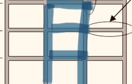
3. However in the perimeter things get confusing. Say you have the frame in the figure, where only the blue moment frame is special, while in the other sections are gravity elements. Would you apply the property modifiers as well to the gravity frames? I am confused here.

Thank you!
Replies continue below

Recommended for you

RE: Cracked sections for gravity elements under seismic action

2
Any member that the moment is over the cracking moment should be reduced.

It really has no bearing on whether you've arbitrarily designated a frame as gravity or seismic resisting.

Deformation compatibility means they need to achieve the same drift performance for both frame types hence gravity frames will still carry some degree of seismic actions, and will crack accordingly, so you should be applying appropriate stiffness reductions to all members. In your picture if the columns and beams are all the same size then they should all have the same reduction factor applied.

RE: Cracked sections for gravity elements under seismic action

(OP)
Hello Agent666, yes I was wondering about this. It is kinda arbitrary what is special and what is ordinary. However, the special detailing requirements should only be satisfied for those elements part of the seismic resisting system.

RE: Cracked sections for gravity elements under seismic action


I fully agree with Agent666 and a pink star to his respond.

Quote (It is kinda arbitrary what is special and what is ordinary. However, the special detailing requirements should only be satisfied for those elements part of the seismic resisting system.)


It is not an arbitrary process to choose some SFRS elements are special , others ordinary. You should choose type of SFRS depending on the SDC. For instance, SMF can be choosen for all SDC category but OMF can be chosen only for SDC A, and B.

I do not know your local code. Some codes allow the use of gravity columns which are not part of SFRS. Still these elements shall be detailed to achieve the same drift performance .

For example, EC 8, distinguishes the structural members that have a secondary contribution to earthquake resistance from the primary members . The contribution of ‘secondary’ members to the lateral stiffness and earthquake resistance of the building is not taken into account in the analysis for the seismic action. Only ‘primary’ members are designed and detailed for earthquake resistance with
the rules of Eurocode 8. However, the secondary members SHALL be designed to maintain support of gravity loads under the most adverse displacements and deformations imposed on them in the seismic design situation .

RE: Cracked sections for gravity elements under seismic action

(OP)
@hturkak however do you apply the same cracked factors for all the elements gravity and seismic resisting elements ?

The source of my confusion is R. With special moment frames we use R=8. Now, those elements part of the SRFS will dissipate the energy which will allow R to be 8. But it is not all of them. For moment frames, it is the perimeter frames that do most of this work. These members will crack much more than the gravity yet we are using the same stiffness modifiers to all the elements in the building.

RE: Cracked sections for gravity elements under seismic action

LJ,

I think HTURKAK's last sentence has answered your question - consider deformation compatibility of all members in the bundle, regardless of individual strength requirement/capability. You should check the state of the stress in the secondary members after deflection, to determine whether the cracked property is appreciate or not.

RE: Cracked sections for gravity elements under seismic action

Quote (LJ_
@hturkak however do you apply the same cracked factors for all the elements gravity and seismic resisting elements ?

The source of my confusion is R. With special moment frames we use R=8. Now, those elements part of the SRFS will dissipate the energy which will allow R to be 8. But it is not all of them. For moment frames, it is the perimeter frames that do most of this work. These members will crack much more than the gravity yet we are using the same stiffness modifiers to all the elements in the building.)


1- Yes.. the cracked stiffness of ‘secondary’ members is used.

2- How did you model the secondary elements ? Modelling of gravity columns somehow simple.. Either assign pin connections at top and bottom joint or set bending stiffness to zero. However, modelling of gravity only beams would need some work. If the beam is continuous and supported on gravity columns , no need to modify any property or connection.

In order to find the design displacements, you SHALL multiply the displacements (found with R value applied ) with deflection amplification factor Cd or maybe with R depending on your local code.

If you post the structural plan with primary SFRS elements and Gravity elements, the discussion may be more helpful.

RE: Cracked sections for gravity elements under seismic action

For the gravity column which is not part of the lateral resistance system, is it checked under combination of gravity load and lateral deformation in ETABS?

RE: Cracked sections for gravity elements under seismic action

The design displacement is probably nowhere near the actual displacement during an earthquake action. Another thing is the fact that no one takes reinforcement into account when determining stiffness (and it significantly influences it). Since primary elements usually have more reinforcement, they'll have even greater stiffness than in the case you're comparing non-reinforced stiffness's. Also, neither the earthquake nor the structure know what is laterally resistant and what is "gravity" so it'll crack at the beginning of an earthquake at latest.

In my opinion because of all this you should always consider secondary elements to have the same stiffness modifiers as the primary ones (anything other than that is just fooling yourself that you actually know what's happening).

RE: Cracked sections for gravity elements under seismic action

Quote (HuynhKeshley ;
For the gravity column which is not part of the lateral resistance system, is it checked under combination of gravity load and lateral deformation in ETABS?)


How did you model the gravity columns? The last time i used ETABS, around twenty years ago.. IMO, you shall develop two models;

In the first model , you may model the gravity columns with assigning pin connections at top and bottom joints or set bending stiffness to zero.. The primary SFRS shall be designed for the effects found with this comb.

The second model, delete pin connections and run again.. gravity columns shall be designed for the effects found with this comb.

RE: Cracked sections for gravity elements under seismic action

Quote (HTURKAK)

The second model, delete pin connections and run again.. gravity columns shall be designed for the effects found with this comb.

I have modeled as the second model.
However, as the response modification factor was assigned, so the deformation output the model is not correct. It should be multiplied by the deflection amplification factor.
Therefore, I would like to understand if ETABS taking into account the deflection amplification factor in design of gravity column.

Do you know which software considering this?

Thanks.

RE: Cracked sections for gravity elements under seismic action

Quote (I have modeled as the second model.
However, as the response modification factor was assigned, so the deformation output the model is not correct. It should be multiplied by the deflection amplification factor.)


I proposed two models.. the first model for designing the primary SFRS.. and the second model for gravity columns..
If you perform the analysis with R= 1.0 you will obtain elastic forces and displacements.
In order to obtain design forces, you will perform the analysis with dividing R.

If you perform the analysis with Cd/R , you will obtain the design displacements..

Red Flag This Post

Please let us know here why this post is inappropriate. Reasons such as off-topic, duplicates, flames, illegal, vulgar, or students posting their homework.

Red Flag Submitted

Thank you for helping keep Eng-Tips Forums free from inappropriate posts.
The Eng-Tips staff will check this out and take appropriate action.

Reply To This Thread

Posting in the Eng-Tips forums is a member-only feature.

Click Here to join Eng-Tips and talk with other members! Already a Member? Login


News


Close Box

Join Eng-Tips® Today!

Join your peers on the Internet's largest technical engineering professional community.
It's easy to join and it's free.

Here's Why Members Love Eng-Tips Forums:

Register now while it's still free!

Already a member? Close this window and log in.

Join Us             Close