×
INTELLIGENT WORK FORUMS
FOR ENGINEERING PROFESSIONALS

Log In

Come Join Us!

Are you an
Engineering professional?
Join Eng-Tips Forums!
  • Talk With Other Members
  • Be Notified Of Responses
    To Your Posts
  • Keyword Search
  • One-Click Access To Your
    Favorite Forums
  • Automated Signatures
    On Your Posts
  • Best Of All, It's Free!

*Eng-Tips's functionality depends on members receiving e-mail. By joining you are opting in to receive e-mail.

Posting Guidelines

Promoting, selling, recruiting, coursework and thesis posting is forbidden.

Students Click Here

Deck Bulb Tees - Simple made Continuous

Deck Bulb Tees - Simple made Continuous

Deck Bulb Tees - Simple made Continuous

(OP)
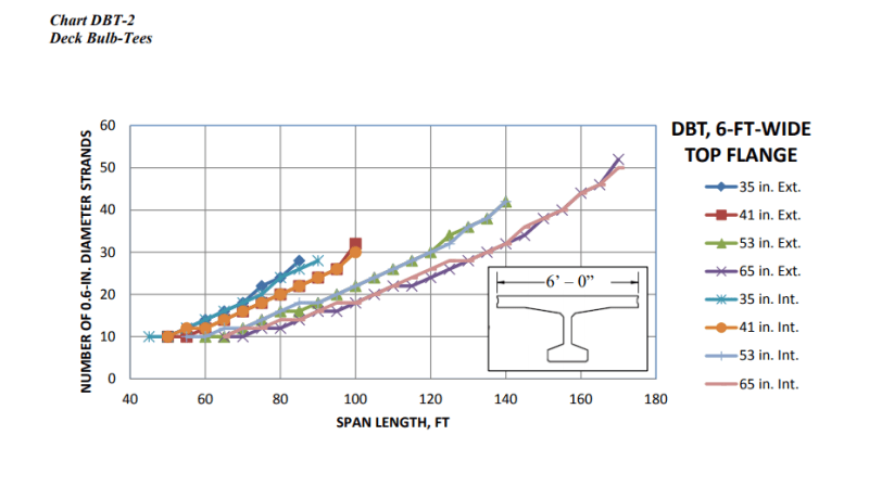
I have a bridge replacement where we are planning to use PCEF bulb tees. As an alternative (looking to shorten construction time) we are looking at a beams with an integrated deck (NEXT, Deck Tees). We have spans of 110' so the NEXT beams are out. Deck tees can go to 140' according to the charts.

With the deck tees, we are assuming that these beams can be used in a simple made continuous for live load span arrangement. For PCEF Bulb tees, continuity steel is place in a structural deck to provide negative moment resistance. Since the deck tees will not have a structural deck, the continuity steel would need to be placed in the top flange. Do anyone know how the connection between steel would be made? Does the continuity steel simply extend into the end diaphragm and is tied together with the closure pour? Is the steel between beams tied together with threaded inserts or couplers? Some other method?


Replies continue below

Recommended for you

RE: Deck Bulb Tees - Simple made Continuous

Unfortunately I cannot speak with any experience to the NEXT beams or Deck Tees since I have never used them. Our State DOT would never allow them. Have you checked with your local precaster to see what forms they have? You have lots of ideas but it might all be for nothing if they can't make it. We've gotten girders from other States before but I don't know if that's typical practice where you're at.

Have you considered a deck bulb tee with a CIP deck? That way you still get a CIP structural deck with continuity over the piers but you don't have any soffit forming costs/delays. Girders set side by side with top flange touching. Not as fast or cheap as a deck tee or a deck bulb tee with longitudinal closure pours but IMO a better product. I have to imagine that the deck tees (double tees) are also going to be heavier than the other options. Any lifting concerns you would have at the bridge location? Do you have crane access to the middle spans?

RE: Deck Bulb Tees - Simple made Continuous

(OP)
I spoke with a local precaster already to get some pricing and availability. Their lead engineer actually called me late yesterday to discuss continuity connection, basically hooks, laps or mechanical connections with the -M steel in the top of the beam is typical.

Deck tees are heavier but probably still manageable, ~110k pick weights. That's another reason we ruled out NEXT beams, those things are 2klf! There will be barge access to the middle spans.

One thing I am noticing with these beams is their performance when used in a continuous for live configuration. The negative moment on the beam causes the beam ends to be over stressed for tension (Service III). The beams perform just fine in a simple span configuration. I am having to go to 10ksi and having to put straight PS strands in the top of the beam web, along with draping the lower web strands to alleviate the tension below the allowable. The precaster said it might be challenging to layout the strands in the stress blocks, but they should be able to work it out. They've seen beams with straight strands in the upper web.

RE: Deck Bulb Tees - Simple made Continuous

Regardless of the type of girder you choose to go with, you are correct in that you need to satisfy the Service III tensile requirements per AASHTO 5.9.2.3.2b-1 for the precompressed tensile zone. However, I have never added straight strands in the web before. Have you tried playing with the CG of the harped strands and/or tried to debond a percentage of the straight strands at the end of the girder. This typically will solve your issue. I know that you've said in other posts that you are more of a steel guy so I wanted to make sure you knew that you could do that. Either way, working with the precaster in arranging the strands is key to get it correct.

If none of it works then you may need to go to a deeper girder.

RE: Deck Bulb Tees - Simple made Continuous


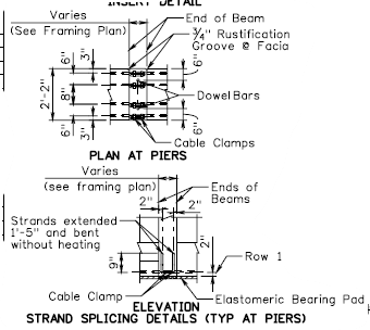
If you can not go to deeper girder, you may go with full continuity with wide in-situ integral crosshead. Our group in past constructed such a bridge some ten years ago. The following picture depicts the set up ( taken from CEB Bulletin 29 Precast concrete
bridges )


RE: Deck Bulb Tees - Simple made Continuous

(OP)
That an interesting detail. Was this because of the end stresses? Seems like it would require some temporary supports to support the beam ends until that end its constructed. I'm trying to simplify and shorten construction, not lengthen it!

FWIW, I quickly looked at a deeper beam when I first saw that 53" deep beams weren't working, but that was problematic too. I went back and just started playing with the strand patterns and adding straight stands in the top to see if I could relief some of the stress and it was working so I just kept adding more and playing with the draped to get it all to work.

Quote (STrctPono)

Have you tried playing with the CG of the harped strands and/or tried to debond a percentage of the straight strands at the end of the girder

Yes, this was the first thing I did. Neither worked on it own. The final result has straight in the bottom flange, draped in the bottom of the web, and straight in the top of the web. No strands crisscross. I had to go all the way to 10ksi AND debond the ends.

What's curious is that these beams are rated per the design charts up to 140'.


The charts are for HL93 and I have the no. strands that the PCI table says I should have (30). It doesn't say however if the beam chart is simple span or made continuous. The beam works as a simple span. It's when it's made continuous that it proves challenging. One solution is to just make them simple spans if I can work out a link slab style detail since I'm trying to avoid joints.

RE: Deck Bulb Tees - Simple made Continuous

Mike I think you are on to something with the link slabs if the beams work as a simple span. You will end up with a cheaper bridge that will perform just fine (i.e. no expansion joints). All the extra strands, draping, additional steel and formwork above all the piers will increase the cost and complexity. The DOT in the state I live in quit using integral pier diaphragms and continuous for live load years ago in favor of link slabs.

Just my 2 cents.

RE: Deck Bulb Tees - Simple made Continuous

(OP)
yeah, the challenge is that there is no structural deck, its just an overlay.

RE: Deck Bulb Tees - Simple made Continuous

Mike, you CAN put a deck on those deck bulb tees. Butt the girders side by side and pour a 6" structural deck on top.

@OSU, is your State DOT's current policy to pour those link slabs with UHPC?

RE: Deck Bulb Tees - Simple made Continuous

Quote (MIKE_311
That an interesting detail. Was this because of the end stresses? Seems like it would require some temporary supports to support the beam ends until that end its constructed. I'm trying to simplify and shorten construction, not lengthen it!)


That system adopted to keep vertical clearance and to utilize the existing precast formwork and bed .It is true that, it will require temporary support.

If you can go with deeper girders, as far as i see, you will need just a continuity slab. The system is essentially simple supported for the girders.

What is the details of pier and abutments?

RE: Deck Bulb Tees - Simple made Continuous

(OP)

Quote (STrctPono)

you CAN put a deck on those deck bulb tees. Butt the girders side by side and pour a 6" structural deck on top.

I know, the whole point of DBTs is to avoid using a CIP deck (trying to shorten construction)! If I need to put on a CIP deck, I may as well just go with option 1, PCEFs.

At this time I'm not sure the time savings is worth the extra cost or detailing effort. The DBTs already require UHPC closures pours which is about 10,000CY locally, we found out yesterday that a contractor may not be able to pick and set these from a barge. So they'd need to construct a crane pad (in wetlands!) to set a larger crane. Conventional methods using PCEFs and CIP deck seem like a better option. There are other aspect of the project where the contractor could save time and we may recommend the state consider adding a incentive clause and let the contractor identify and propose an ABC alternative if they can identify one.

great discussion topic though!

RE: Deck Bulb Tees - Simple made Continuous

STrctPono

No. The concrete for link slab is the same as the rest of the deck. The deck area over the piers is not cast until the rest of the deck is complete. They call it a "closure pour", but I think the entire deck could be placed from one end to the other without stopping. Why add more transverse construction joints if you don't need to? The extra reinforcing steel and the bond breaker on top of the girders is what makes the link slab work.

RE: Deck Bulb Tees - Simple made Continuous

Here is WVDOH continuity detail. Never used it.

I'm sure you have seen the slideshow presentation by Mr. Scarlata with the NYDOT for link slabs? The one link slab we have designed here did not require UHPC but the DOH insisted on using it.

Link

I thought I recall that the AASHTO LRFD Bridge Manual either Edition 5 or 6 went into great detail on prestressed beam continuity. It was removed after being in only one or two editions.

RE: Deck Bulb Tees - Simple made Continuous

I have project that's starting construction, rehab of a 26 span viaduct, all simple spans, 10 joints will have UHPC link slabs. Most of the piers are being replaced because they're in worse shape than the ones in Jim S' presentation but a few of the good ones had to be replaced because they couldn't handle the lateral forces with the new bearing configurations. You have to be careful with staged deck construction. On my project we're replacing the piers fascia to fascia in one shot but the deck replacement, including link slabs, is being done in 7 stages. Below the existing deck at the link slab locations we have to temporarily tie adjacent stringers together. The ties act as a link slab until the deck is replaced.

3Fan - I used that detail once, about 20 years ago on Coalfields Expressway. One of the last WVDOH projects I did.

RE: Deck Bulb Tees - Simple made Continuous

Ya, we've found WV is many years behind other DOT's in details and CAD. It certainly allows designers to be creative when there are limited standards. Enjoy working with them when there is time to properly get
through a project.

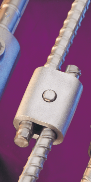
Sorry back on topic, we had to splice bars coming out of the top of box beam at piers once and used a quick wedge mechanical splicing system. Might work for your situation.


RE: Deck Bulb Tees - Simple made Continuous

Quote (3Fan)

Ya, we've found WV is many years behind other DOT's in details and CAD. It certainly allows designers to be creative when there are limited standards. Enjoy working with them when there is time to properly get
through a project.

As a designer, I enjoy working as a consultant for a DOT that has little to no standard bridge details. As you stated, it allows the designer to actually be creative as opposed to choosing details out of a cookbook like some baking recipe. I would not be long for the career if I found myself in a job where this were common practice. For me, the detailing process is the most enjoyable part of my work.

The only standard detail I wish our DOT would come up with is a MASH tested aesthetic TL-3 bridge railing. Instead of stealing other State's designs, it would be nice if they could acquire some funding and program a project where they design and test a concrete bridge railing to be used on all future historic bridge replacement projects.

Quote (MIKE 311)

I know, the whole point of DBTs is to avoid using a CIP deck (trying to shorten construction)! If I need to put on a CIP deck, I may as well just go with option 1, PCEFs.

Except you have little to no deck forming cost so you actually do save time. But I do agree with you regarding the point that you should just go with PCEF and CIP deck.

Red Flag This Post

Please let us know here why this post is inappropriate. Reasons such as off-topic, duplicates, flames, illegal, vulgar, or students posting their homework.

Red Flag Submitted

Thank you for helping keep Eng-Tips Forums free from inappropriate posts.
The Eng-Tips staff will check this out and take appropriate action.

Reply To This Thread

Posting in the Eng-Tips forums is a member-only feature.

Click Here to join Eng-Tips and talk with other members! Already a Member? Login


News


Close Box

Join Eng-Tips® Today!

Join your peers on the Internet's largest technical engineering professional community.
It's easy to join and it's free.

Here's Why Members Love Eng-Tips Forums:

Register now while it's still free!

Already a member? Close this window and log in.

Join Us             Close