Continue to Site

Eng-Tips is the largest engineering community on the Internet

Intelligent Work Forums for Engineering Professionals

  • Congratulations cowski on being selected by the Eng-Tips community for having the most helpful posts in the forums last week. Way to Go!

V-joint to slender RC column at mid-height

Status
Not open for further replies.

Ingenuity

Structural
May 17, 2001
2,374
We have a few bridge structures in my area with Freyssinet hinges and I have seen Mesnager hinges too, but I have never seen a V-joint in a slender RC blade column to a parking structure.

WESTPOINT_MALL_-_COLUMN_V-JOINT_zamosh.jpg


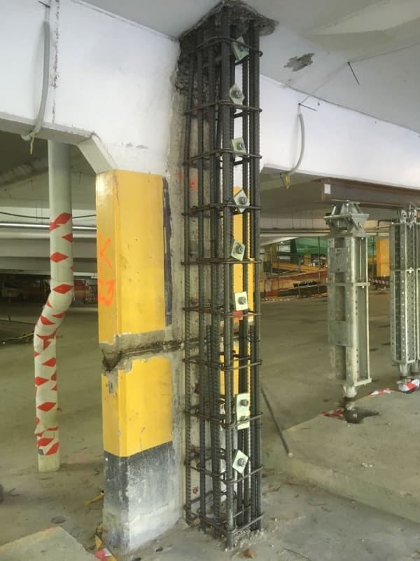
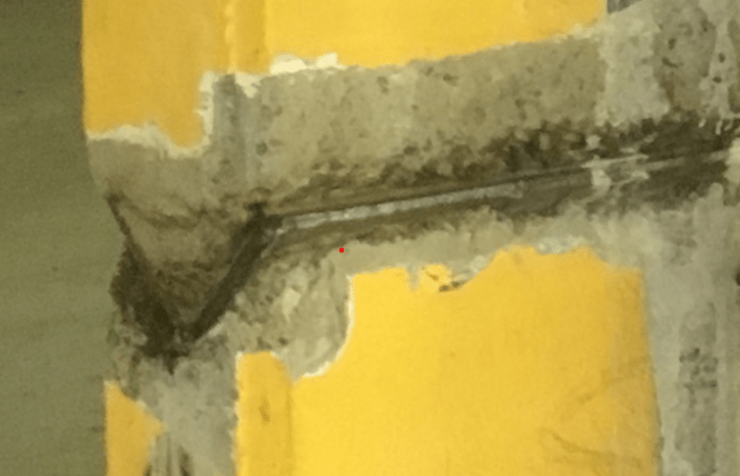
A closer-look at the V-joint:

vjoint_fa5rxx.png


Parking structure is located outside Sydney, Australia. Built early 70's - one of the earlier parking structures to one of Australia's first shopping malls.

I believe floor framing is prestressed beams in long direction, one-way slabs in transverse.

Interesting detail. Anyone seen one in the 'wild"?
 
Replies continue below

Recommended for you

No, all cast-in-place concrete - columns, beams, slabs.

The V-joint appears to be cast-in nested steel angles - based upon the corrosion of the exposed edges.

 
No, never seen a detail like that. Can you get access to the design drawings?
 
Somebody getting super creative about fascilitating unrestrained slab shortening? Viscerally, it feels like a stability nightmare. Although, with the right attention to detail, one could robustly cantilever up and down to the hinge.

Are there a lot of these things in the building? Do we know what the intended building lateral system is? Do we know if the angles are welded together or welded to rebar?
 
I think the joint was intended to be a sliding-joint for the longitudinal-axis, to permit movement due to restraint and axial effects of prestress in the beams.

I don't think it was intended as a rotational hinge, as such a hinge (about the minor-axis of the column) with nested steel angles would tend to crush/spall the outer concrete near the bottom angle edges.

I don't have access to the design drawings, unfortunately. The parking structure recently went through an extensive structural remedial upgrade (including grouting many PT tendons that were left un/partially grouted for near 50 years), which I discovered via an email flyer for the Concrete Institute of Australia on an upcoming conference entitled: "Investigating Construction Defects and Failures".

 
KootK said:
Are there a lot of these things in the building?

Not sure, but more than 1.

KootK said:
Do we know what the intended building lateral system is?

With parking structures designed in the 70's in Sydney, probably not an especially defined lateral system. I do know that recent upgrades have placed new RC walls in strategic positions. With the addition of new RC columns connected to these slender blade columns, seems to suggest 'supplemental' strengthening. I know the structure but have not been there for many years, and if I recall correctly the original engineer has retired so the engineer doing the upgrade may have been a bit nervous with the original detail, or how it was performing.

KootK said:
Do we know if the angles are welded together or welded to rebar?

I don't think (speculation) the angles are welded together, and hopefully there is embedded rebar welded to each angle.

 
If the original engineer still breathes, you should take him out for a beer and some shop talk. There's no statute of limits on bad-assery of this magnitude as far as I'm concerned.

With respect to the new column, are you interpretting that as something akin to a bone splint?
 
KootK said:
If the original engineer still breathes, you should take him out for a beer and some shop talk. There's no statute of limits on bad-assery of this magnitude as far as I'm concerned.

I may well do that when I visit AU next - assuming it is the engineer I think it is. When I was at uni and studying PT he was locally famous for doing interesting things with PT. One of them was actually to this shopping mall where he used vertical PT in columns to 'hang' lower floors to upper floors.

KootK said:
With respect to the new column, are you interpreting that as something akin to a bone splint?

Possibly. Back in the day, AU codes used to have special 'out' clauses for fire resistance (FR) to wall/columns, where, if the aspect ratio was 4:1 (or maybe 3:1, cannot remember) you could call it a wall and only have to comply with wall FR details - much less than column FR requirements. This may be the logic for the upgrade engineer 'splinting' the column, or the column may not meet current code slenderness ratios, as built - not really sure.
 
How do you suppose that detail relates to the Portal Method or the Cantilever Method? These were approx. methods of lateral analysis, which both assume a point of contraflexure at the mid height of the columns? That detail certainly defines a point of zero moment, a hinge, in those columns, in that direction. I’ll have to think on this a little longer, it’s been since about the late 60’s or early 70’s since I last used those approx. analysis methods.
 
Ingenuity said:
Back in the day, AU codes used to have special 'out' clauses for fire resistance (FR) to wall/columns, where, if the aspect ratio was 4:1 (or maybe 3:1, cannot remember) you could call it a wall and only have to comply with wall FR details

Those clauses still exist in the current code.
 
Status
Not open for further replies.

Part and Inventory Search

Sponsor