Continue to Site

Eng-Tips is the largest engineering community on the Internet

Intelligent Work Forums for Engineering Professionals

  • Congratulations cowski on being selected by the Eng-Tips community for having the most helpful posts in the forums last week. Way to Go!

The "purpose" for definition of FOS and AME (ASME Y14.5 2009) Conical /Tapered features 3

Status
Not open for further replies.

dtmbiz

Aerospace
Sep 23, 2008
292

Unfortunately the ”purpose” for the need to define certain and specific terms and concepts", which would be helpful in determining the “intent” of the standard’s definition regarding inclusion and /or exclusion for features considered in respect to those definitions and concepts. More specifically regarding FOS and AME for this discussion relative to conical and tapered features.

Here are my general points for discussion. I hope others will post theirs.

Purpose of FOS: (Feature of Size) My understanding of its purpose is to identify features that have center planes, axis and center points in order to locate and orient tolerance zones.

Purpose of AME: (Actual Mating Envelope) My understanding of its purpose is to establish a produced FOS’s actual location and orientation of it’s center plane, axis or center point by use of a AME Datum Simulator (gage) in order to verify compliance with the defined tolerance zone by comparing the true feature's vs. the produced feature's location and orientation of axis, center plane or center point.

It is also my understanding that applied geometric controls to an FOS, “other than size” can only be verified after the produced feature’s has been verified to be within size limits.

Conical and tapered feature’s: In a previous thread (thread1103-460248) there are arguments that conclude that these type features cannot be classified as features of size because in the case of a cone (conical feature) there is a limit to expansion or contraction about the apex, and similarly a limit to intersection of tapered surfaces beyond their intersection.


Disagreement with argument that 'conical and tapered surfaces are not FOSs because an AME cannot be defined":
Conical and tapered surfaces can and do have an AME in the physical world (vs a purist mathematical theoretical world) which can identify a produced FOS axis or center plane.
The AME’s Datum Simulator would not expand or contract beyond the limit of the apex of a conical surface or intersection of tapered surfaces whether or not they actually occurred within the size limits of the feature’s extent. Concluding that the apex of a conical surface and the intersection of tapered surfaces would be to one side of the tolerance limits and would be the minimum or maximum allowance which therefore would be the minimum or maximum limits of contraction or expansion of an AME. (internal / external feature). Expansion or contraction is limited to be within limits of size vs. infinite or unlimited

**** Also would like to mention in relevance to the FOS definitions, specifically around the standard's use of “may”, and the definitions of words ; may, must , will, shall in the engineering environment (English that is). “May” is a permission word that “allows” and is not mandatory. “Shall” is a “mandatory requirement” which is not used in definition of FOS

 
Replies continue below

Recommended for you

dtmbiz said:
Conical and tapered feature’s: In a previous thread (thread1103-460248: Orientation of a center plane of a tapered feature) there are arguments that conclude that these type features cannot be classified as features of size because in the case of a cone (conical feature) there is a limit to expansion or contraction about the apex, and similarly a limit to intersection of tapered surfaces beyond their intersection.

To be exact, the main argument against tapered features being features of size was the "unlimited offset" from the true profile to the unrelated actual mating envelope simulator during the simulation process, as was shown in this illustration. I do not wish to drag the discussion from that thread to this new one, and sorry if anyone finds it inappropriate, but for me, there are still open questions: What does the "true profile" do in that process? This is not a tolerance validation process, but a process intended to derive an axis from a considered feature, i.e. performed prior to tolerance validation that requires anything "true" (true position or true orientation may be more relevant anyway, but then how does the shown offset matter?) And if "true profile" is already there, why doesn't it follow the feature and/or the envelope simulator? Been looking for clues in the standard to no avail.

As I mentioned in that thread, I have my own doubts about the classification of tapered features as FOS:
The main concern is that whereas for a cylindrical feature size adjustment of the simulator makes sense, because a too large or too small UAME or RFS datum feature simulator will fail to contain the feature as it will not make reasonable amount of contact with it (e.g. an oversized internal cylinder being used as a simulator for a smaller external cylinder only makes contact along a line, and as a result the derived axis will not be centered to the actual feature), a fixed theoretical UAME or datum feature simulator of sufficient length can be fully mated (and properly constrained to centering by contact) to a tapered feature of any range of local sizes, as long as the included angle is appropriate. This doesn't sit well with the standard's requirement of datum feature simulators for RMB datum features of size to be adjustable in size.
Another concern is regarding the lack of examples and established ways to specify tolerances of location and orientation for tapered features, intended to validate derived geometry (center planes and axes) to tolerance zones.
 

Burunduk

This thread is intended to focus on the valid definitions and concepts within the Y14.5 text that have been approved by the ASME Y14.5 committee.
This why I would like to approach this discussion in a "fresh" way, via the "purpose" and definitions of FOS and AME as insight for validating what is a FOS
(particularly the irregular type) and "its" AME (which I am not convinced is mandatory)

I do not wish to "drag" the referenced thread into this thread either for the exact example that you have cited, "unlimited offset".
The terms and concepts that are not part of Y14.5 were used in that thread to validate personal opinions and assertions are not found in Y14.5.
Those types of arguments only clutter and distract from what Y14.5 does state and define. "Containment concept" can be added to the mentioned unofficial / unapproved ASME
The term; "Unlimited offset" is not used in Y14.5, the term "unlimited" is used once in the text of the "Adoption Notice" page.

This thread referenced that thread because it was a recent example of not accepting conical features and opposing tapered surfaces as FOSs because of allegedly not
being able to define an AME for them.


This thread was started to analyse these types features of size and a defined AME for them.
I am questioning if according to Y14.5's definitions that a FOS is required to have an AME. Thus the attention to the defintions that used the term "may" which
is not a mandatory requirement. Also as an example that a FOS is not required to have an AME, screw threads and their pitch circle default is posed.

In addition to using terms and concepts that are not part of the authorized Y14.5 text, while even going a step further to use some "process" outside of the
application of Y14.5 and its text, in order to base interpretations on is not legitimate.

As far as interpretations regarding "a process" to interpret and or for application of Y14.5 that is not found in the text either; not in the terms mentioned.
The process for applying Y14.5 is a "decision diagram" in Appendix E.
The word "process" is used relative to special notes,"process equipment", and in regards to SPC controls.

A premise for developing GDT over the years was to apply dimensions and tolerances relative to function and mating interfaces and to depart from the practice
of applying dims and tols based on "manufacturing processes". Knowing that background logic would also apply to consideration but NOT application
per inspection processes.

To my recollection in the referenced thread,"True profile" in the Tolerance of Profile Section 8, was also misused and conflated with other definitions (sorry i mentioned that thread now)
e.g. conflating "true profile", "true geometric form" and "similar perfect counterpart"

A number of posts in that thread didn't adhere to discussion supported by ASME approved content of Y14.5, I hope this thread will.

 
dtmbiz said:
This thread is intended to focus on the valid definitions and concepts within the Y14.5 text that have been approved by the ASME Y14.5 committee.
This why I would like to approach this discussion in a "fresh" way, via the "purpose" and definitions of FOS and AME as insight for validating what is a FOS
(particularly the irregular type) and "its" AME (which I am not convinced is mandatory)

I totally support this idea and would like to see a purely standard-based discussion evolving here on this subject.

dtmbiz said:
This thread was started to analyse these types features of size and a defined AME for them.
I am questioning if according to Y14.5's definitions that a FOS is required to have an AME. Thus the attention to the defintions that used the term "may" which
is not a mandatory requirement.
Also as an example that a FOS is not required to have an AME, screw threads and their pitch circle default is posed.

1.3.32.2 Irregular Feature of Size:
"(a) a directly toleranced feature or collection of features that (nonmandatory: may contain or be contained by an actual mating envelope that is a sphere, cylinder, or pair of parallel planes)
(b) a directly toleranced feature or collection of features that (nonmandatory: may contain or be contained by an actual mating envelope other than a sphere, cylinder, or pair of parallel planes)"

I suppose then, that the mandatory requirement is only "a directly toleranced feature or collection of features" for both types of irregular features of size?


Burunduk

In reference to your support of this standard based discussion we are on the same page.

In reference to the mandatory / non- mandatory definitions of FOS interpretation focusing on the language "may", my interpretation is the same.

The reasoning for asking "what is the purpose" of a FOS is to find out other's understanding of "why even define an FOS"?

I am not necessarily looking for agreement with me, rather what do others have as an understanding and how that understanding
effects their views for application of geometric controls, which is important because it is relevant to understanding where a
feature's tolerance zone is located and oriented.

i.e. Considering a cylindrical hole:

1) The tolerance zone is located about the the true profile of the cylinder for a Profile of Surface control. Size, location, orientation and form are controlled.

2) The tolerance zone is located about the the axis of the cylinder for a Tolerance of Location control. Location and orientation are controlled.

Now for the "purpose" of an AME.

1.3.25 Envelope said:
A similar perfect feature(s) counterpart of smallest size that can be contracted about an external feature(s)
or largest size that can be expanded within an internal feature(s) so that it coincides with the surface(s) at the highest points...[/quote

It is a prescribed definition in order to generate the inverse of a produced feature. Which is used for immobilization of a part and to calculate bonus tolerance
for geometric controls use of MMC or LMC.

Following comments are considering "finite" features while excluding theoretical mathematical geometric definitions that are boundless. (infinite);

I personally do not see how an AME cannot be applied to a diametrically complete conical feature or opposing tapered surfaces equally disposed about a center plane. finite(having physical extents)
Maybe that it inst possible for a "partial conical surface" similar to requiring a cylindrical feature to be a completely or diametrically enclosed feature ?
Or opposing and equally disposed tapered surfaces about a center plane that have an included angle greater than an angle that violates a definition of "opposing" ?

Relevant to the ASME standard, what would be other interpretations ?
 
dtmbiz said:
I personally do not see how an AME cannot be applied to a diametrically complete conical feature or opposing tapered surfaces equally disposed about a center plane.

Same here.

dtmbiz said:
In reference to the mandatory / non- mandatory definitions of FOS interpretation focusing on the language "may", my interpretation is the same.

Actually, I meant to question the "may = nonmandatory' approach in regards to irregular FOS definition. This stripped-down definition doesn't look like it can get us farther than stating that any feature, planar surface included, can be classified as an irregular feature of size (both type (a) and (b)).

Notice that the text says "directly toleranced feature". Not the same as the regular feature of size - "associated
with a directly toleranced dimension".
 
FYI:

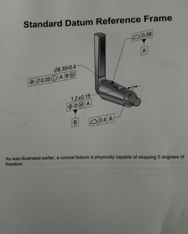
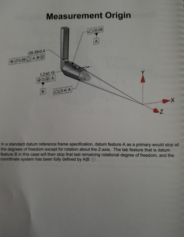
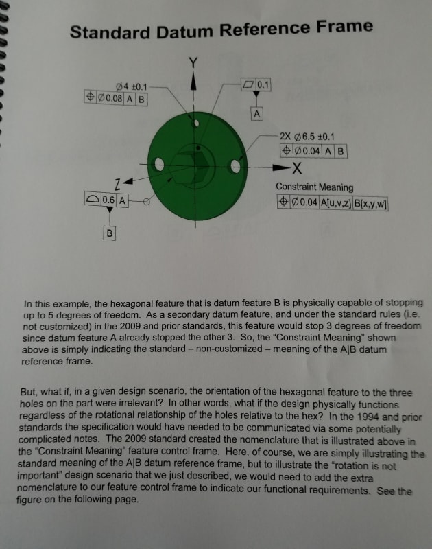
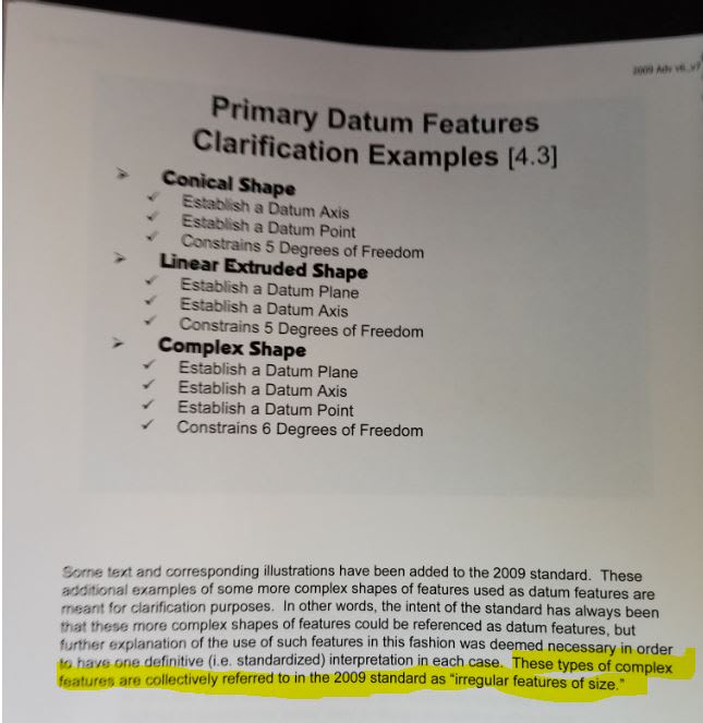
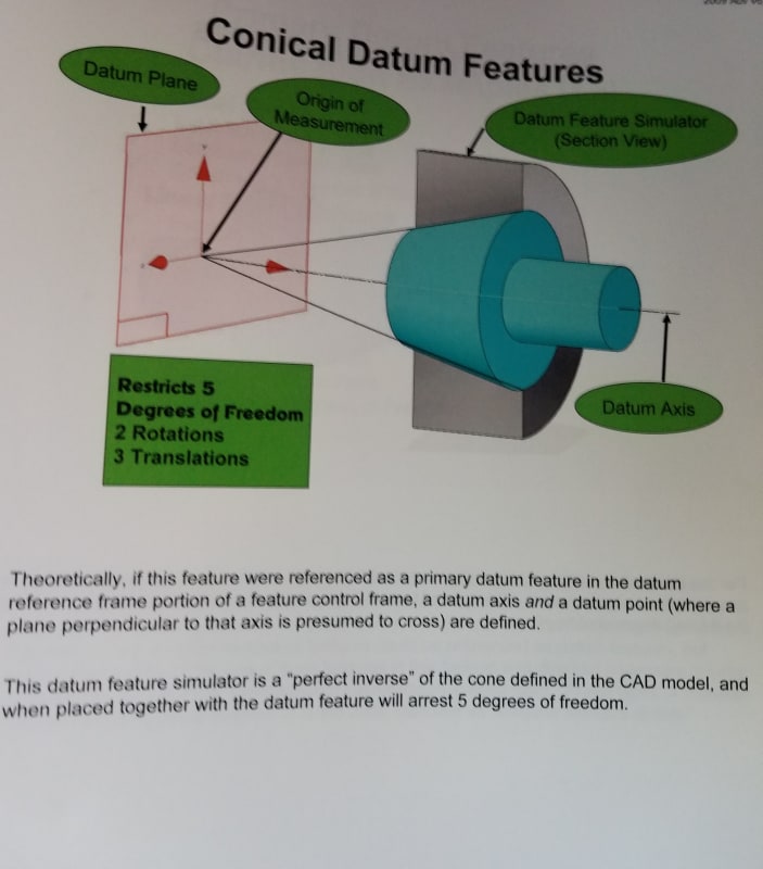
Take it from the Pros... Conical features are FOSs (Found images from course I took years back.. AGI)

A.ScrnSht.GDT.FOS.Irregular_yujrgb.jpg


A.ScrnSht.GDT.FOS.Irregular.Conical.Simulator_kjwryh.jpg
 
dtmbiz, very interesting figures!
Does this training material have any examples of position or orientation tolerances applied to conical or flat-tapered features?
 
Excellent - now show how variations in the size of the cone relate to allowable movement. Preferably without including changes in the cone angle which would also create a variation; What exactly would be the single distinguishing "size" value for a cone?

Also, that's really taking it from a single "pro". Does not seem to be the consensus, which would suggest that it is not derivable from the standard. Not much of a standard if the interpretation isn't.
 
Burunduk, 3DDave

The material comes from AGI Applied Geometrics Inc. "Advanced GDT Training" course book.
I took the training almost 10 years ago presented by Norman D. Crawford (GDTP S-0386). Also worked with him in a professional engineering environment.
It was my pleasure to be "mentored" by Norm during that time. I believe he has left AGI and has his own company in Cleveland Tennessee.

Mark Foster is AGI President and was the "1st ever" (GDTP S-0114) to pass the ASME administered professional exam.
Mark participates regularly in ASME Y14.5 committee meetings.

AGI and Norm's company are top rate and would highly recommend getting AGI's training. Google them.
I am not a solicitor for them and its been years since I have any contact with AGI or Norm

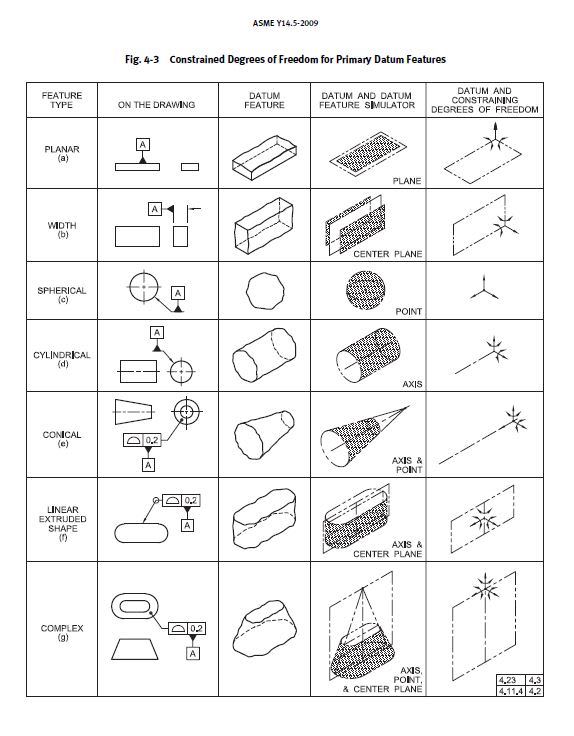
Burunduk, the below chart is in ASME 14.5 2009. If you can do a conical feature of size, it seems the same principles would apply
to "inclined" (tapered for conical) opposed surfaces equally disposed about a center plane.

A.ScrnSht.GDT.DOFs.Chart_im2qfa.jpg
 

All,

Hopefully I did not violate any forum rules. Just wanted to provide graphics for highly contested definitions in ASME Y14.5 2009 interpretations (FOS)

Burunduk,
As I believe I have mentioned earlier in the "purpose" for an FOS is to define axis, center planes, and center points.
Basic dimensions would be applied to these complex features axis, center plane or center point likewise from these complex shape's Datum Feature Simulator

3DDave
I did not write "Pro", I wrote "Pros" in reference to "many other professionals" that I have worked with relative to ANSI and ASME Y14.5 in my lengthy career.
I have never based my "understandings" on "consensus". "The standard" stands on its own regardless of "consensus" by numbers.
I consider "mob rule" to be mindless [pirate]

This is not directed toward you personally however someone I admire greatly commonly references the following;
"A man convinced against his will, is a man that remains unconvinced"

Thanks to all for your posts and interest

 
Please detail the answer of how to determine the unambiguous size.

Also note that the trainers don't seem to have done so.

The standard stands as a common reference so that everyone can come to a single understanding. If there is some other understanding then that is a big problem.

It is up to you to build a case, not for others to disprove a conclusion you've drawn without providing proof.
 
dtmbiz,
Using conical datum features to derive establish an axis is acceptable by everyone and hasn't been questioned, but many believe that this datum axis is derived established without the application of an actual mating envelope, so it still isn't good enough to support the "cone=feature of size" argument, and to make others (me included) convinced of their own free will :). In my opinion, what can support such a conclusion is examples from training material or professional literature that show orientation or position controls applied to conical (or flat taper) features, preferably RFS, to control the location and/or orientation of a derived axis/center plane. Being able to be controlled this way, is what I consider one of the "purposes" of the feature of size concept. Unfortunately, I never went through high-quality training like you seem to have, so I mainly rely on the examples in the standard itself. If I had access to such materials - position/orientation tolerance application is where I would be looking for support.

Edit: the distinction between "established" and "derived" is important.
 

Burunduk

To be clear I have no intention to "convince others". Merely presenting my views. Others can "take 'em or leave 'em".

Also I am fortunate to have had considerable training by very knowledgeable instructors with a few having ties to the ASME Y14.5 committee,
and all having real life experience in Engineering, Quality, inventions and patent holders.

Personally I value those experiences because they were more than instructors or "trainers" (makes me think of animals [puppy]) rather they
are "teachers" that help students "grow in learning" in a way to be confident in there own (student's) abilities.

In the context of this forum, what I can do is to "attempt to convey my understandings /interpretations" relative to ASME Y14.5 and support those interpretations
as in agreement with ASME Y14.5 by presenting verbal and written communications and graphic examples when possible.

My understanding of an AME in relationship to a FOS is that by establishing an FOS's a referenced datum(s) at RMB via a Datum Feature Simulator, that
Datum Feature Simulator is also the means to define an AME for any given produced feature.


4.11.4 Specifying Datum Features RMB said:
(a) Primary Datum Feature: Diameter RMB. The datum
is the axis of the datum feature simulator of the datum
feature. The datum feature simulator (or unrelated
actual mating envelope) is the smallest circumscribed
(for an external feature) or largest inscribed (for an
internal feature) perfect cylinder that makes maximum
possible contact with the datum feature surface.
See
Figs. 4-3, illustration (d); 4-11; and 4-12.

In the context of an Unrelated AME the simulator is stand alone ("Free State" if you will).
In the context of a Related AME the simulator is configured in respect to a DRF.


I am also considering the standards use of the "may" wording. Wondering if the intent is to acknowledge the lack of need for an AME for MMB and LMB ?
Still 'considerable considering' to do [ponder]


Consensus, "others" ? How does one know if one is representing "others" views of a "consensus" ?

The US Science and Engineering Workforce - FAS.org said:
In 2016, the latest year for which Occupational Employment Statistics survey data are available, 6.9 million people were employed in the United States as scientists and engineers, accounting for 4.9% of total U.S. employment.Nov 2, 2017


dtmbiz said:
I am also considering the standards use of the "may" wording. Wondering if the intent is to acknowledge the lack of need for an AME for MMB and LMB ?
Still 'considerable considering' to do ponder

Considering is over.. The above wouldn't be the case because the AME is needed for Datum Shift / Displacement allowance for MMB or LMB when
a datum modifier is used within a geometric control.

 
Paragraph 4.11.4 (a) which was quoted, and also (b) and (c) convey that specifically for cylindrical, width-type, and spherical primary datum features it is true that "datum feature simulator" = "UAME".
None of these shapes is a cone or a flat taper.

While it may seem somewhat natural that the rule for cylinders can be extended to other surfaces of revolution, I would be cautious to do so, because the language of the standard is very specific in this case, and besides there are important geometrical differences: apart from the somewhat ambiguous meaning of "...smallest circumscribed (for an external feature) or largest inscribed (for an internal feature).." where there is no single size value to be smallest/largest, a conical datum feature simulator can be non-adjustable, and will still act the same as collet-like device with a conical opening to contain the feature, as long as the included angle is correct and the simulator covers the entire diametrical range of the considered feature (if it is a theoretical simulator, and Y14.5 talks mainly of these, there is no reason why it won't). That is while para. 4.5.2 imposes a requirement on a datum feature simulator: "(f) adjustable in size, when the datum feature applies at RMB." All this seems problematic.
 
Burunduk

Yes the cylinder reference to compare the Datum Feature Simulator and an AME as the same, is one that
directly connects the FOS and AME standard's "intent" for the subject. I believe it is reasonable logic to believe is true for all FOS’s.

Size limits are required to be verified first before an AME is defined or any attempt at validating geometric controls is made.

The expansion/contraction of a similar perfect (gage tolerances) counterpart contacts the produced feature's "high points" to define
a "mating size" per se (Actual Mating Envelope) for a produced feature. Not multiple variations of size through out the feature's surface imperfections.

The "envelope size" is used relative to how the feature mates (assembles) to its corresponding mating feature.

For me this not problematic. What is "problematic" is part definition "without" GDT.

 
dtmbiz said:
The expansion/contraction of a similar perfect (gage tolerances) counterpart contacts the produced feature's "high points" to define
a "mating size" per se (Actual Mating Envelope) for a produced feature. Not multiple variations of size through out the feature's surface imperfections.

The "envelope size" is used relative to how the feature mates (assembles) to its corresponding mating feature.

So what is the "mating size" / "envelope size" for a tapered feature?
 
Status
Not open for further replies.

Part and Inventory Search

Sponsor