Design of Compression Member
(OP)
Dear All,
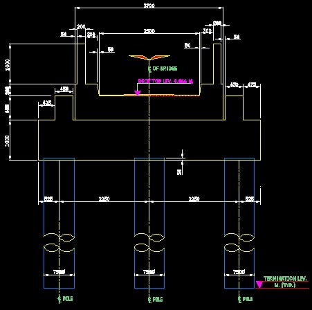
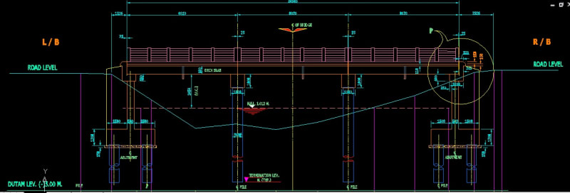
I am designing a 8.02 meter clear span R.C.C. slab bridge with 2.5 m clear carriageway. I am providing there 3 no. 750 mm diameter pile as pier. The pier will be continued so that it acts also as pile foundation. No separate pile cap is being provided in this case or the pile cum pier are directly extending from the pier cap which is a 1.1 m x 1.0 m x 5.5 m R.C.C. beam. In this connection if someone explain me how to design the pier as per SP 16 it will be helpful to me.
With Regards,
Ujwal Mandal
RE: Design of Compression Member
Rod Smith, P.E., The artist formerly known as HotRod10
RE: Design of Compression Member
BridgeSmith
Sorry sir, i am new to this forum and not habituated with this. Sorry for late respond. You are right. Kindly give me suggestion.
RE: Design of Compression Member
retired13
Sorry sir, sorry for late reply, I am new to this forum. kindly pardon me. yes you are right. i want to design this as per Indian Standard. IS SP 16.
with regards
Ujwal Mandal
RE: Design of Compression Member
For the piers (what we would call "bents", don't ask me why), we would iterate to get the depth into the soil that produces an equivalent cantilever for one of the major load cases, using structural analysis software for the frame analysis and P-y curve analysis software (Allpile or Lpile) to model the effect of the lateral soil resistance on the shaft. We find the length of a fixed-base column that has similar stiffness to the column plus the shaft embedded in soil. It's usually fairly close to the first moment reversal (inflection point) of the shaft in the soil). This allows us to process all the load cases in the structural analysis software using the same, simplified model.
Sometimes we take the simpler and conservative approach of applying the moments and shears at the groundline assuming the column fixed at that point, and apply those to the top of the shaft in Allpile or Lpile to get the maximum reactions in the shaft.
Rod Smith, P.E., The artist formerly known as HotRod10
RE: Design of Compression Member
In my opinion, BridgeSmith has clearly layout a path allow you to tackle the problem, you need to walk through the path yourself. If it is too difficult for you to start, you shall seek help from your seniors, and/or talk to whomever handed you the assignment at the first place. This space (forum) is not supposed to hold you hand step by step. You can always come back later with specific/pointed question though.
RE: Design of Compression Member
I don't want to be rude or insulting, but if you need step-by-step tutelage for this design, you are likely not qualified to be taking it on. Bridge design is a specialized branch of structural engineering that takes extensive training to do properly and safely. It is not to be taken on by a novice without close oversight by a qualified and experienced bridge designer. Again, I don't want to be condescending; I just don't want you to get in over your head.
Rod Smith, P.E., The artist formerly known as HotRod10
RE: Design of Compression Member