×
INTELLIGENT WORK FORUMS
FOR ENGINEERING PROFESSIONALS

Contact US

Log In

Come Join Us!

Are you an
Engineering professional?
Join Eng-Tips Forums!
  • Talk With Other Members
  • Be Notified Of Responses
    To Your Posts
  • Keyword Search
  • One-Click Access To Your
    Favorite Forums
  • Automated Signatures
    On Your Posts
  • Best Of All, It's Free!

*Eng-Tips's functionality depends on members receiving e-mail. By joining you are opting in to receive e-mail.

Posting Guidelines

Promoting, selling, recruiting, coursework and thesis posting is forbidden.

Students Click Here

20,000 PSI System Odd PID Loop Behavior

20,000 PSI System Odd PID Loop Behavior

20,000 PSI System Odd PID Loop Behavior

(OP)
We have a 20K pressure washing system installed in our plant. The system is run via a high pressure pump that draws from a water reservoir. On startup, the system starts by recirculating water through a dump valve back to the reservoir. The system then turns on a PI control loop with the output of the dump valve clamped at 21% (~4,000 psi) for ~30 seconds to drive air from the system and allow operators to check for leaks at low pressure. After 30 seconds, operators enable "High Pressure", which removes the clamp and allows the PI loop to control without the clamp. Setpoint is typically 19,000 psi.

Initial settings were P: 0.3 %/%, and I: 0.05 rep/sec. Bias is 0%. The controller is a standard ISA position PID loop.

Valve Position = Kc * (Error + Error * dt/Ti + Td * Derivative) + CV Bias.

The tuning parameters are: P = Kc, I = Kc/Ti,
I then tuned it, eventually reaching P: 0.2 %/% and I: 0.3 rep/sec. Reducing P below 0.2 %/% completely eliminated that cycling, and the new controller values have very little (but still some!) cycling. Reducing even further completely eliminated cycling, with a smooth ramp, but resulted in a much longer time to achieve SP.

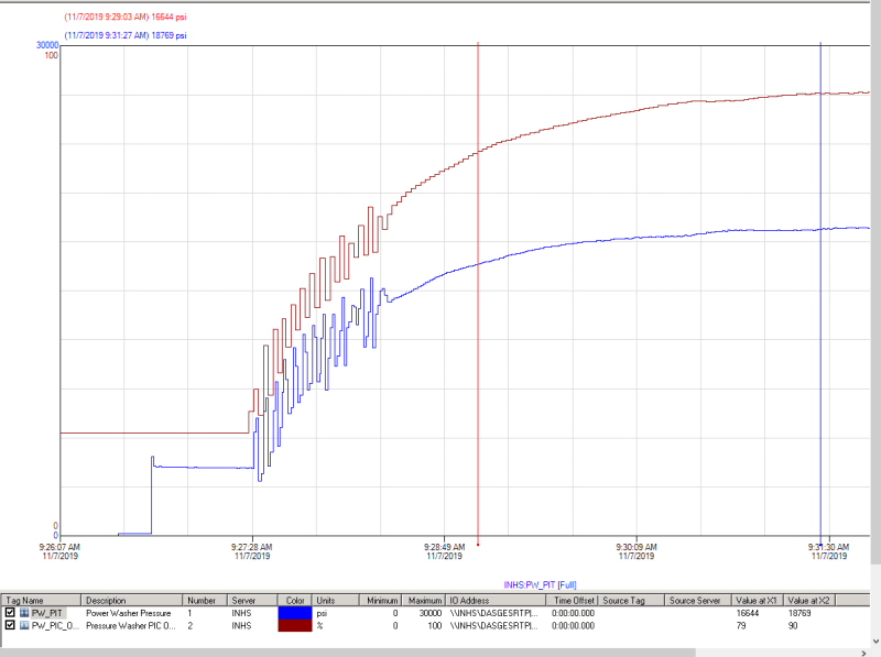
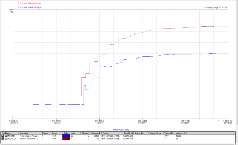
Upon releasing the clamp, the below behavior was observed. The second graph is the final tuning parameters.

Initial:


Final:


With initial settings, the system would cycle, then eventually smooth out. Given the loop is PI only (no derivative control), I don't see any reason that anything would drive the valve back down to make it cycle like it did. The only reason I see as a possibility is this: The sample rate for recording and display is only 2 seconds. It is possible that system pressure went above setpoint due to integral windup during the clamp, causing the valve to re-close quickly, with all of this occurring before the screen or historian updated. It is odd, though, that the historian recorded fairly repeatable values - if the cycling frequency were not the exact same as the sampling frequency, it should have recorded some very high values. The controller also does not have any output rate of change limiter enabled that would only allow the valve to open X%/second

What is causing this cycling phenomenon?

Edit: New information. The current bit as described below is currently set a "0". Since we are starting at 100% error on startup (pressure is near 0 and setpoint is 19,000), the valve is calling for >21% open, leading to BIT 4 setting a negative initial integral value. Does that make sense?

Bit 4: Anti-reset windup action. When this bit is 0, the anti-reset-windup action uses a reset (integral term) back-calculation. When the output is clamped, the accumulated integral term is replaced with whatever value is necessary to produce the clamped output exactly.

When the bit is 1, the accumulated integral term is replaced with the value of the integral term at the start of the calculation. In this way, the pre-clamp integral value is retained as long as the output is clamped. This option is not recommended for new applications. Refer to CV Amplitude and Rate Limits below.

RE: 20,000 PSI System Odd PID Loop Behavior


you might compare the piston cycle rate to you pulsations,

RE: 20,000 PSI System Odd PID Loop Behavior

(OP)
I have, and it's not the reason for this. The pump has 5 pistons, each offset on stroke, and they stroke at 400 rpm. The cycles are on the order of a couple of seconds. The pressure fluctuations are being caused by the control valve jumping around, but I can't tell why it is jumping around.

RE: 20,000 PSI System Odd PID Loop Behavior

Something it your system is either malfunctioning or operating substantially faster or than the loop can respond. Your plant's response is on the order of 150 seconds, but your control input is on the order of 6 seconds.

TTFN (ta ta for now)
I can do absolutely anything. I'm an expert! https://www.youtube.com/watch?v=BKorP55Aqvg
FAQ731-376: Eng-Tips.com Forum Policies forum1529: Translation Assistance for Engineers Entire Forum list http://www.eng-tips.com/forumlist.cfm

RE: 20,000 PSI System Odd PID Loop Behavior

The 'P' component may be either proportional band or gain, one is the inverse of the other. If your gain is .2% I would expect a slow response. Tuning usually requires you to try various combinations of tuning constants until you get the response you want. BTW, I can not envision a process where you would not want 'anti reset windup'.

Brad Waybright

It's all okay as long as it's okay.

RE: 20,000 PSI System Odd PID Loop Behavior

if problem still persists, you might take a look at the time traces of actual valve position, and process pressure.

RE: 20,000 PSI System Odd PID Loop Behavior

I remember from graduate course, in regulation there is always trade off between stability and precision.
PID is most adequate to obtain both.

Not sure I can help, just my two cents...

Life is not about waiting for the storm to pass. It's about learning dance in the rain.

RE: 20,000 PSI System Odd PID Loop Behavior

the issue still persists or solved alreay?
I cannot help either?just update for learning

More than 500.000 Parts available ship worldwide in fast delivery time (PLC, HMI, Inverters, Servo Drives, CNC, Motors - Encoders, Software, Low Voltage...
https://panasonicservomotor.com/HG-KR23/

RE: 20,000 PSI System Odd PID Loop Behavior

(OP)
CNCservo,

I have not made any headway on this. The cycling phenomenon would exist if I increased the gain again to a higher level. As it is, I've reduced the gain until the cycling was no longer evident. I'm still completely perplexed as to why the system cycles in the first place at higher gains; it is a PI controller, and it certainly isn't going much above setpoint (because doing so would blow the rupture disc on the pump).

If PV is below setpoint for a PI controller when the loop is initiated, there should not be anything that drives the valve lower - both the P and the I will be opening the valve. The only thing I can think to check is have our controls check the built-in formula to make sure the P and the I have the same sign (both should be positive wrt error).

RE: 20,000 PSI System Odd PID Loop Behavior

Not all problems can be solved by only tuning a controller. You have to fully understand the process, and each mechanical component and sensor. Time delays between sensing the process variable, and the control action having an effect on what the sensor reads, is the main limitation on how responsive it is possible to be. Most valves also have mechanical hysteresis.

RE: 20,000 PSI System Odd PID Loop Behavior

Again, your processor control loop is responding too fast to the stimulus. Your process is taking about 28 seconds to respond to a basic control change, but your process loop is outputting a new control change every second.

TTFN (ta ta for now)
I can do absolutely anything. I'm an expert! https://www.youtube.com/watch?v=BKorP55Aqvg
FAQ731-376: Eng-Tips.com Forum Policies forum1529: Translation Assistance for Engineers Entire Forum list http://www.eng-tips.com/forumlist.cfm

RE: 20,000 PSI System Odd PID Loop Behavior

Quote:


Not all problems can be solved by only tuning a controller. You have to fully understand the process, and each mechanical component and sensor. Time delays between sensing the process variable, and the control action having an effect on what the sensor reads, is the main limitation on how responsive it is possible to be. Most valves also have mechanical hysteresis.
Yes! It is more helpful to post the set point, target pressure , actual pressure and control output as a function of time. The control output is necessary for determining if there is a dead time.

It would also be good to have the valve position.


Peter Nachtwey
Delta Computer Systems
http://www.deltamotion.com
http://forum.deltamotion.com/

RE: 20,000 PSI System Odd PID Loop Behavior

(OP)
PNachtwey: The posted graphs are of actual pressure and output going to the valve. We don't have actual valve position - there is an I/P converter. Target pressure is 19,000 psi during the run. Unfortunately the historian only records the data every 2 seconds, so I don't have more granular data than what is provided above.

Just a further note on the system design - the control valve is a 3-way valve that dumps excess water back to the reservoir tank. Change in system pressure is nearly instantaneous with valve position changed due to the incompressibility of water.

IRStuff, I'm not sure I understand you. The change in pressure is near instant with change in valve position, so process response is extremely quick. If I were to change valve position manually from 15% to 80%, pressure would immediately jump from 4,500 psi to ~18,000 psi. The largest lag in the system is likely valve travel speed and/or sensing element response time. If you are talking about making loop changes before the system has a chance to feed back the response (valve travel time + sensing element change time + processing time vs loop update rate), then I get where you are coming from. The loop update rate needs to be a good bit slower than the sensed response for the loop to be stable. FYI, the loop update rate is 2 seconds.

I'm inclined to agree with Compositepro (and maybe IRStuff, too, if that's the point you are making?). It's likely that something physically in the loop (valve travel time, pressure sensor element update time?) is too slow for the loop udpate rate, and is causing instability.


RE: 20,000 PSI System Odd PID Loop Behavior

TiCl4-
PID control has changed a lot from it's earliest implementations employed using electro-mechanical and pneumatic control. The PIDE instruction in Allen-Bradley Logix controllers applies the gain parameter to the process velocity (or rate-of-change if you will) instead of the error or PV signal by itself. It's very likely that any newer PID device employs a much more sophisticated and complex algorithm than what we learned years ago. That makes predicting the effect of a single tuning parameter more difficult. Also, my experience shows that the final tuning constants normally end up being unusually small, at least as far as the gain component is concerned.

Brad Waybright

It's all okay as long as it's okay.

RE: 20,000 PSI System Odd PID Loop Behavior

Basically, yes; it's obvious that your controller are oscillating because it's being told to open the valve, and on the very next cycle, it's closing the valve. In the meantime, the overall system takes about 30 times longer to reach a stable operating point.

TTFN (ta ta for now)
I can do absolutely anything. I'm an expert! https://www.youtube.com/watch?v=BKorP55Aqvg
FAQ731-376: Eng-Tips.com Forum Policies forum1529: Translation Assistance for Engineers Entire Forum list http://www.eng-tips.com/forumlist.cfm

RE: 20,000 PSI System Odd PID Loop Behavior

At 19,000 psi, water is _not_ incompresssible; it has a finite bulk modulus.
Also, at that pressure, the pipe is stretching.
That makes two springs that are probably not accounted for in your system model.

Mike Halloran
Corinth, NY, USA

RE: 20,000 PSI System Odd PID Loop Behavior

Great post, Thanks for the information

Red Flag This Post

Please let us know here why this post is inappropriate. Reasons such as off-topic, duplicates, flames, illegal, vulgar, or students posting their homework.

Red Flag Submitted

Thank you for helping keep Eng-Tips Forums free from inappropriate posts.
The Eng-Tips staff will check this out and take appropriate action.

Reply To This Thread

Posting in the Eng-Tips forums is a member-only feature.

Click Here to join Eng-Tips and talk with other members! Already a Member? Login


Resources

Low-Volume Rapid Injection Molding With 3D Printed Molds
Learn methods and guidelines for using stereolithography (SLA) 3D printed molds in the injection molding process to lower costs and lead time. Discover how this hybrid manufacturing process enables on-demand mold fabrication to quickly produce small batches of thermoplastic parts. Download Now
Design for Additive Manufacturing (DfAM)
Examine how the principles of DfAM upend many of the long-standing rules around manufacturability - allowing engineers and designers to place a part’s function at the center of their design considerations. Download Now
Taking Control of Engineering Documents
This ebook covers tips for creating and managing workflows, security best practices and protection of intellectual property, Cloud vs. on-premise software solutions, CAD file management, compliance, and more. Download Now

Close Box

Join Eng-Tips® Today!

Join your peers on the Internet's largest technical engineering professional community.
It's easy to join and it's free.

Here's Why Members Love Eng-Tips Forums:

Register now while it's still free!

Already a member? Close this window and log in.

Join Us             Close