×
INTELLIGENT WORK FORUMS
FOR ENGINEERING PROFESSIONALS

Contact US

Log In

Come Join Us!

Are you an
Engineering professional?
Join Eng-Tips Forums!
  • Talk With Other Members
  • Be Notified Of Responses
    To Your Posts
  • Keyword Search
  • One-Click Access To Your
    Favorite Forums
  • Automated Signatures
    On Your Posts
  • Best Of All, It's Free!

*Eng-Tips's functionality depends on members receiving e-mail. By joining you are opting in to receive e-mail.

Posting Guidelines

Promoting, selling, recruiting, coursework and thesis posting is forbidden.

Students Click Here

Rubber cylinder to hyperboloid

Rubber cylinder to hyperboloid

Rubber cylinder to hyperboloid

(OP)
Hi All,

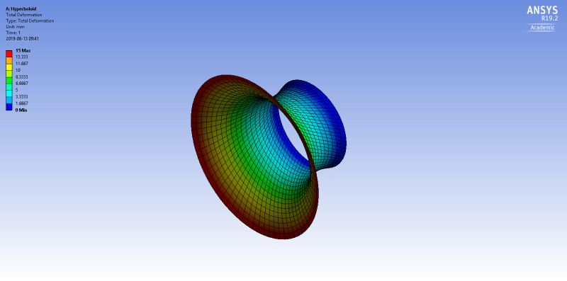
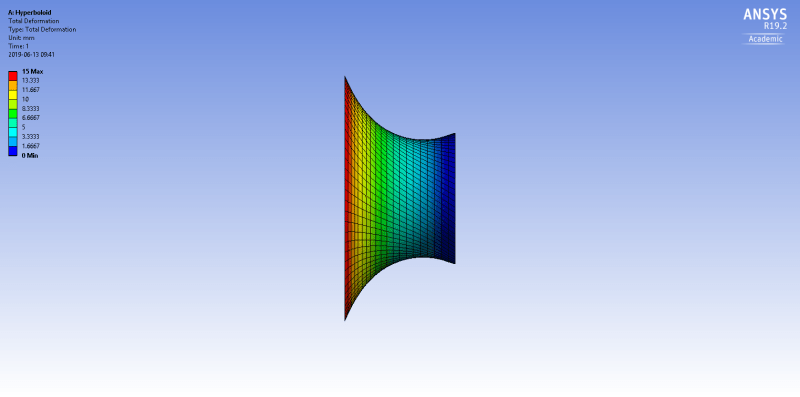
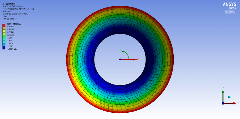
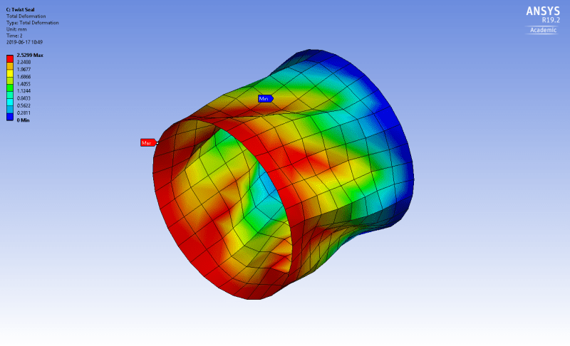
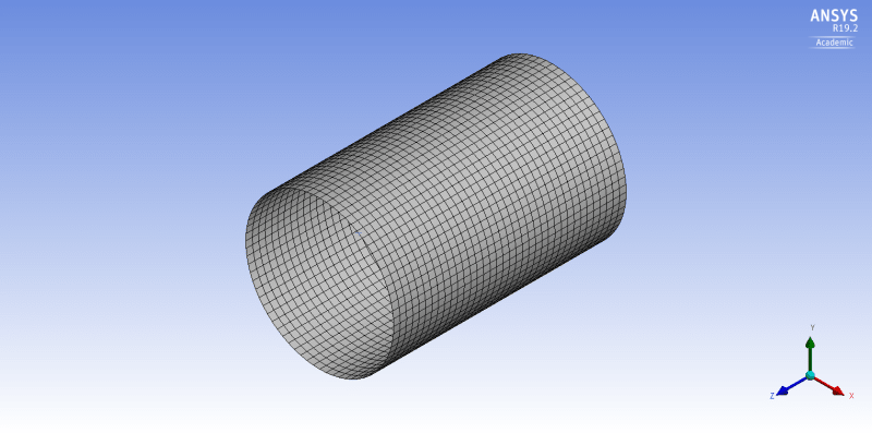
I have a cylindrical rubber piece that I want to twist into a hyperboloid.
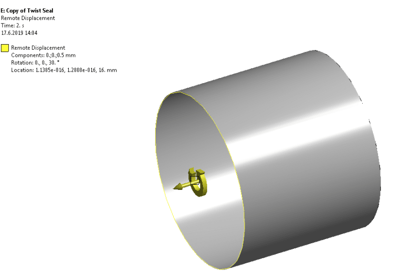
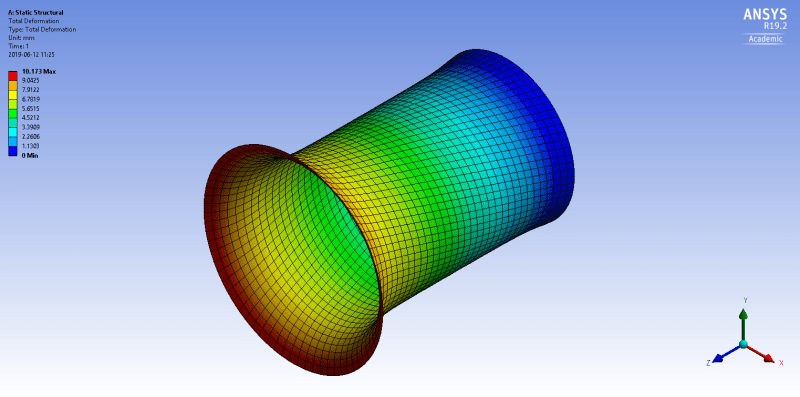
I tried fixing a circular edge, and applying a rotational displacement of 10° to the other edge but
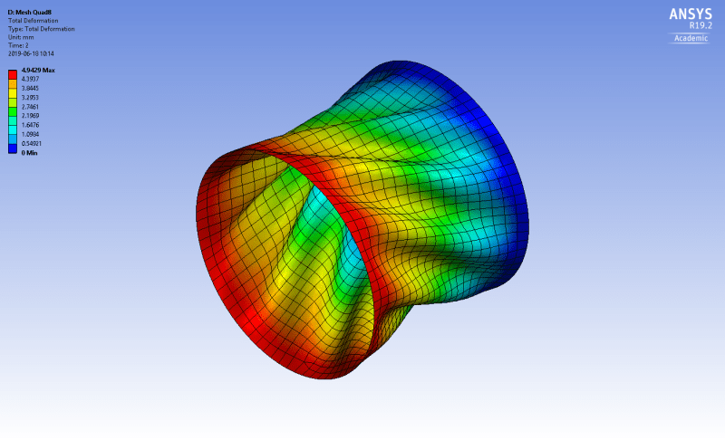
the deformation seems quite unrealistic. I would expect the necking to happen about halfway.
Also the required rotation is 30 deg, but solution won't converge.
Any tips on how to set up this problem is greatly appreciated.


Project files:
https://files.engineering.com/getfile.aspx?folder=...

Thanks

RE: Rubber cylinder to hyperboloid

Maybe you are trying to calculate problem in linear static. Linear assumption (small displacements and small rotations) give large errors when you are use rigid elements (RBE2 or RBE3 you use to apply load or fix other end) and rotation.
Try to on nonlinear solution.

RE: Rubber cylinder to hyperboloid

(OP)
I wouldn't know how to go about fixing that.
For your info, I did turn on large deflection mode in analysis settings

RE: Rubber cylinder to hyperboloid

If can, please share that project.
Everyone can check it.

RE: Rubber cylinder to hyperboloid

(OP)
I added link to project files to original post

Thanks

RE: Rubber cylinder to hyperboloid

You need to also restrain the left hand circular edge in Z and radial leaving only rotational free. Does ANSYS not have cylindrical coordinate systems ? Would seem the ideal use of such.

Like this:

RE: Rubber cylinder to hyperboloid

(OP)
Hi rother,

I inserted a cylindrical coordinate system and set axial and radial displacement to 0. Rotation set to 15 mm.


It sure helped, at least now the necking is happening in the middle, as expected.
Still when I look at the deformed shape (true scale) the edge expands out in radial direction:


Any ideas why this might be happening?

Also in real life when twisting the rubber sheet overlapping folds start to appear.
I was able to reproduce this in ANSYS by tweaking dimensions of cylinder and playing with mesh settings
but it seems a bit inconsistent. I cannot get the right result every time.

Thanks

RE: Rubber cylinder to hyperboloid

When you say "set axial and radial displacement to 0" do you mean you applied a prescribed displacement of 0 magnitude or do you mean you constrained the nodes to be fixed in axial and radial directions ?

I don't use ANSYS, we have NX Nastran & Algor. In our world 0 described displacement and fixed are different things. 0 described displacement simply means no displacement is applied, i.e the nodes are free to move.


RE: Rubber cylinder to hyperboloid

I would check the value for the radial displacement (directional deformation in the x direction). The scaled plot can be misleading.

RE: Rubber cylinder to hyperboloid

(OP)
I checked the radial displacement and indeed it's really small at the top edge.
The plot scale was set 1.0 (True scale) so maybe just a visualization artifact of ANSYS?


RE: Rubber cylinder to hyperboloid

Seems that the program is using the total deformation value to visualize the scaling. You can also use remote displacement boundary condition if you want to define the angle.

RE: Rubber cylinder to hyperboloid

These are hard problems. What is the error message? Distorted elements?
How much is the max plastic strain before the analysis stops?

RE: Rubber cylinder to hyperboloid

(OP)
Most of the time the errors are due to highly distorted elements.
I thought that refining the mesh would help instead it seems to make things worse.
I didn't even bother to add self contact, because solving time goes up exponentially.
Kind of stuck at the moment...

RE: Rubber cylinder to hyperboloid

I am getting the analysis to converge to 30 degrees using linear tets and element size 1mm.
By the way, check the location of the reference node of the remote displacement boundary condition.
In this case the location does not matter though.


RE: Rubber cylinder to hyperboloid

A couple of things that will help.

-Use QUAD8 elements, since this is a thin body (higher order QUADS, to capture curvature better, ..). You can set that in mesh and element order (set to quadratic).

-Use stabilisation since the structure undergoes some form of instability (as seen in your image above).

-Move your remote point location in z top about the opposite edge (Z= ~0.0157 m).

With that and with more initial steps (100)+maximum steps (1000) for step 2, it is fine (solves for 32 degrees) just make sure that the stabilisation energy is not too high in the end (should be small compared to the elastic energy).

RE: Rubber cylinder to hyperboloid

(OP)
Thanks guys, this really helped!

RE: Rubber cylinder to hyperboloid

You are more than welcome Davide

RE: Rubber cylinder to hyperboloid

(OP)
What if I want to take this even further and go a full half rotation (180°).
Is there any chance it will converge?

RE: Rubber cylinder to hyperboloid

Why not to try it?

RE: Rubber cylinder to hyperboloid

And if it does not use transient dynamics (including some stabilisation as you did for the static case), and if that does not do it either then use explicit (quasi static)

RE: Rubber cylinder to hyperboloid

(OP)
Tried many times but found it impossible to get convergence using static structural for more than 30° rotation.

Eventually, I could get to twist 165° using Explicit Dynamics with damping control to remove unwanted dynamic effects.


Red Flag This Post

Please let us know here why this post is inappropriate. Reasons such as off-topic, duplicates, flames, illegal, vulgar, or students posting their homework.

Red Flag Submitted

Thank you for helping keep Eng-Tips Forums free from inappropriate posts.
The Eng-Tips staff will check this out and take appropriate action.

Reply To This Thread

Posting in the Eng-Tips forums is a member-only feature.

Click Here to join Eng-Tips and talk with other members! Already a Member? Login


Resources

Low-Volume Rapid Injection Molding With 3D Printed Molds
Learn methods and guidelines for using stereolithography (SLA) 3D printed molds in the injection molding process to lower costs and lead time. Discover how this hybrid manufacturing process enables on-demand mold fabrication to quickly produce small batches of thermoplastic parts. Download Now
Design for Additive Manufacturing (DfAM)
Examine how the principles of DfAM upend many of the long-standing rules around manufacturability - allowing engineers and designers to place a part’s function at the center of their design considerations. Download Now
Taking Control of Engineering Documents
This ebook covers tips for creating and managing workflows, security best practices and protection of intellectual property, Cloud vs. on-premise software solutions, CAD file management, compliance, and more. Download Now

Close Box

Join Eng-Tips® Today!

Join your peers on the Internet's largest technical engineering professional community.
It's easy to join and it's free.

Here's Why Members Love Eng-Tips Forums:

Register now while it's still free!

Already a member? Close this window and log in.

Join Us             Close