Miami Pedestrian Bridge, Part X
(OP)
A continuation of our discussion of this failure. Best to read the other threads first to avoid rehashing things already discussed.
Part I
thread815-436595: Miami Pedestrian Bridge, Part I
Part II
thread815-436699: Miami Pedestrian Bridge, Part II
Part III
thread815-436802: Miami Pedestrian Bridge, Part III
Part IV
thread815-436924: Miami Pedestrian Bridge, Part IV
Part V
thread815-437029: Miami Pedestrian Bridge, Part V
Part VI
thread815-438451: Miami Pedestrian Bridge, Part VI
Part VII
thread815-438966: Miami Pedestrian Bridge, Part VII
Part VIII
thread815-440072: Miami Pedestrian Bridge, Part VIII
Part IX
thread815-451175: Miami Pedestrian Bridge, Part IX
Check out Eng-Tips Forum's Policies here:
FAQ731-376: Eng-Tips.com Forum Policies
RE: Miami Pedestrian Bridge, Part X
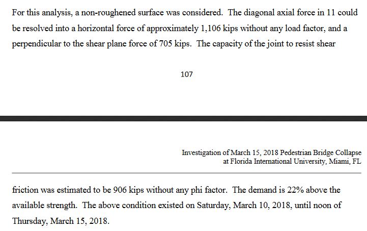
P107 of OSHA report determines shear capacity of joint as only 22% deficient. Further down, when comparing 11 with 2, they mention that they have included Member 1 & 12 reinforcement when calculating shear capacity. No where, however, do they mention specifically which bars they've included and excluded (for lack of development length). They could be a lot clearer here. I also think that it's debatable whether Member 12 steel should be included, and certainly not all Member 12 steel, as a good portion of the member lies outside of deck.
RE: Miami Pedestrian Bridge, Part X
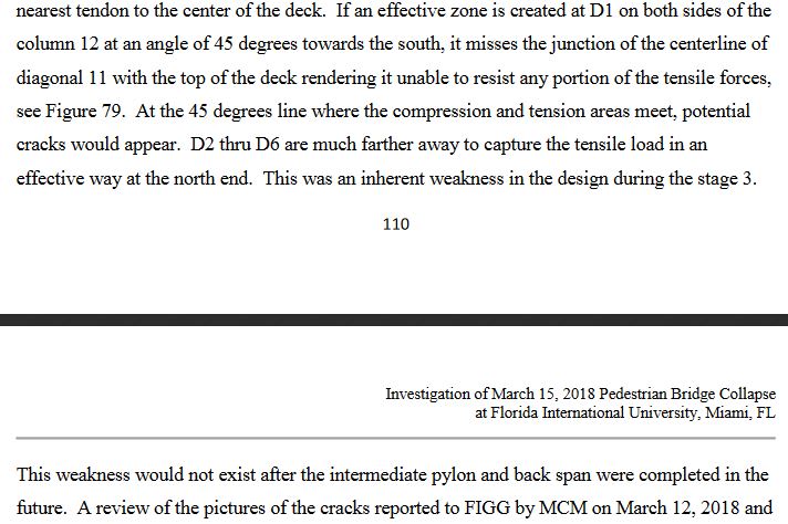
P110. I realize they are here focused on Member 11 when pointing out the deficiencies w.r.t. shear lag between deck PT and horizontal force from diagonal. The way it's worded, however, they make it sound like shear lag concerns are gone once pylon is cast. This is obviously not the case, as Member 2 will still have these concerns.
RE: Miami Pedestrian Bridge, Part X
As I recall, "40YearsExperience" was addressing exactly that in his posts, and suggested reinforcing wrapping behind 11/12 and extending into the PT compressed zones.
Member 2 at the South End has a better chance of having some more capacity - the location of PT strands and the 45 degree lines are the same as at 11, but the column member 1 is 36" and flush with the end of the deck, so we gain a foot there (12 extends past the end of the deck), then member 2 is 36" deep and at a flatter angle so we pick up maybe 2 feet there. And the drawings call for 5-#7 hoops with the chance for proper embedment above the shear plane. But a dedicated calc is the only way to know. And how much development can we count on when clipping the compressed zone of the PT ?
However, the OSHA photos of the North end diaphragm show cracking like I think Pate was addressing in his PowerPoint show, so he was right to be concerned about that. It just was not the most critical thing to address at that point in time.
RE: Miami Pedestrian Bridge, Part X
Transfer of Tensile Forces to the Deck, OSHA pg 110.
In members 2 and 11 the first PT is centered 1'-8" (+1/2") from C/L of structure. OSHA addressed the influence of this on page 110, as previously discussed.
The North span of 96 feet has the first PT at 4'-8" from C/L, meaning the end diagonals 14 and 23 are far from any PT zones. Looks like the same problem, just less load.
RE: Miami Pedestrian Bridge, Part X
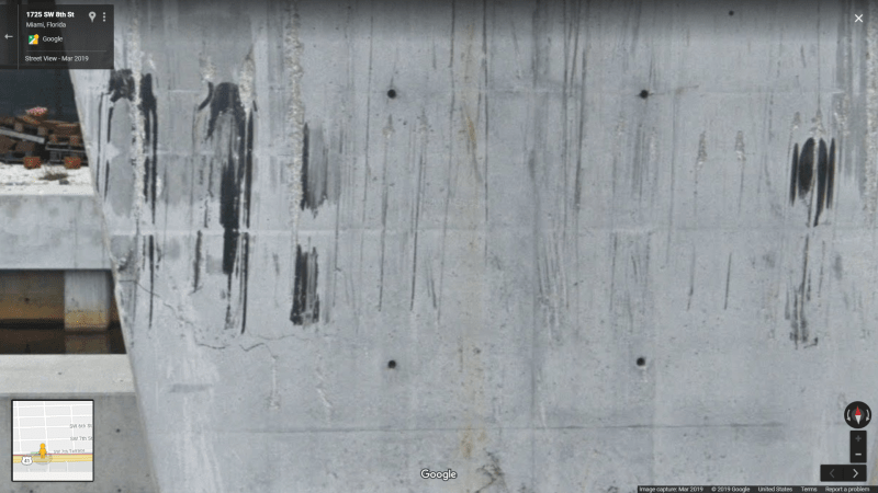
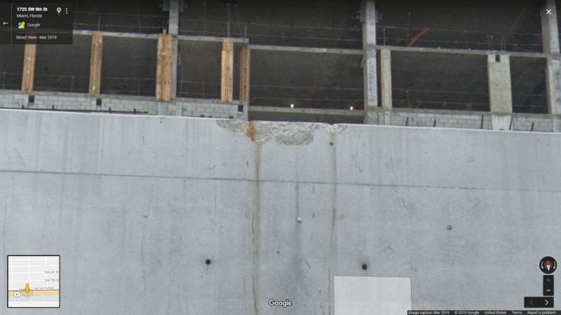
Chipping on pier edge appears to be directly related to punch through.
RE: Miami Pedestrian Bridge, Part X
Well, enough said on that but what I am so amazed with is the OSHA report, in my opinion, has finally pulled the gloves off and said what needed to be said:
1. The design was lacking in structural strength.
2. The design did not provide redundant load paths.
3. The EOR had plenty of information and notification the bridge section erected was showing signs of structural failure.
4. The peer review system failed not only with the CEI (Bolton, Perez and Associates) but also with the "independent" review hired by FIGG - Louis Berger. Even, FDOT and FIU should have put more engineering horsepower into their review of the plans and ongoing construction.
5. The very experienced construction team, Munilla Construction Management, on site did not strongly speak up and call an alarm.
6. Many firms, entities, professional people (with very storied and prestigious degrees and licenses) failed to step up and be "Captain Obvious"; their years of experience and expertise were not put to use when it was most important.
So, how did all this go down? Did this relatively "simple" pedestrian bridge get a quick glance over for the calculations and analysis? Hey, it is "only" a pedestrian overcrossing. Did the hope and interests of FIU to promote their ABC engineering program cause their peer review to take a back seat to getting a landmark iconic bridge - even if the design is a risky concrete truss? Isn't there a term or theory for no one willing to challenge a perceived expert or group of experts? I see this not as a lesson for pointing a finger at a villian, but as a lesson for learning to not to get lulled into complacency.
Mr. Pate, is a licensed professional engineer and the FIGG team is composed of multiple PEs; they are very skilled and their record and past designs speak to that. They are very educated and experienced.
Ms. Figg, may not be a licensed engineer, but she has an engineering degree(s) and whether she is licensed as a professional engineer is not the point. She hires very capable people to do the actual engineering, probably without micro-managing them - give 'em the project and turn 'em loose. She continues to run the company her father started; more than likely with a great sense of pride and honor.
Bolton, Perez and Associates and Louis Berger were supposed to have used their engineering expertise to check the work of Mr. Pate and his team. Did they get lulled into giving the analysis a quick glance because of the reputation of FIGG and Denney Pate? The OSHA report calls out the Louis Berger review very pointedly as being insufficient and improper for ensuring load conditions for all phases of construction were reviewed.
FIU with their academic team should have looked more closely at the plans and the ongoing situation. But somehow they coasted and only asked light questions and did not show the engineering expertise that would be expected of a center of bridge engineering. Did they let the FIGG reputation blind them? Did FDOT engineering figure this is all covered by all the aforementioned experts and they wouldn't need to look too closely?
Even the construction company with the more often "boots on the ground" view didn't step back from the project and call for a halt until the cracks and failing structure were addressed. They totally flew by the numbers given by the EOR and since none of the other reviewers objected strongly maybe MCM chose to stay mum, also.
I'm taking this as a lesson for me - though I only design desktop type analyzers. For now on, when I present my calculations and designs for review, I will strenuously ask for thorough review and comment/criticism. This bridge failure has emphasized to me, as a designer/engineer there are times you can be so invested in your design you may miss the obvious and unintentionally precipitate a disaster!
RE: Miami Pedestrian Bridge, Part X
My career included some experience with prestressed concrete.
When still in college, the company I worked for designed an auto dealership in 1962 using 10 ft tees, and with parking on the roof. I did some drafting on that project. About 1966 I designed the additional floor to create a second parking level. In 1995 the School District wanted to use the building for an Adult Education Center, and I established procedures for injecting cracks, full scale load testing, and then the design to current codes for approval by The California State Division of Architect as a school. The remodel required taking down the PT in the topping slabs, creating a two story atrium with skylight, and restoring PT in the remaining sections.
We also did PT design for a small precast fabricator, and developed the necessary stressing frame and procedure for casting bonded prestressed box girders 4 ft by 84 foot length, on a riverbank.
Along the way I learned that prestressed structures are alive, and simple is the best. Strain compatibility, shear lag, walls that steal the PT forces and then crack themselves -all are problems to be addressed.
A concrete truss? I can imagine bigtime problems.
First concern is post-tensioning the deck, causing about 5/8 inch shortening in this bridge. From center out that is 5/16" at the base of 2 and 11. Neither of which really want to shorten, and so cracks develop at their connection to the deck. To minimize this, one could consider stressing the canopy concurrently, keeping the top and the bottom shortening balanced. Reducing the distance between nodes on the deck and the canopy would have caused the thing to "grow" in height, of course. And that would decrease the angles between the diagonals, with strains and possible cracking. Then there is the stressing of only the tension diagonals - how do we suppose the compression diagonals are going to react to the shortening of the stressed tension in the adjacent diagonals? Rotation at the canopy nodes, perhaps? Then there are the joints, with high compression forces under the anchor plates, sometimes crossing of PT, and the need for confinement reinforcing. Perhaps 40YearsExperience could look at this and make a recommendation, using Mohr's Circle. I am asking in earnest. There is a lot going on in these joints.
Faced with these obstacles, I recommend refusing the project.
In it's final stage, the structure will (and for a brief period did) appear simple - but that is deceptive, as has been proven.
RE: Miami Pedestrian Bridge, Part X
The chipping could possibly be due to the impact of the overhanging portion of 12 as it was dragged over the edge.
I can't see any evidence of extra shims at the center, so I guess MCM did not get to that before the collapse. It is good that they were not working on that Friday afternoon.
RE: Miami Pedestrian Bridge, Part X
Emphasis mine.
This excerpt from NASA's handbook sums up my entire motivation for visiting this thread.
https://ntrs.nasa.gov/archive/nasa/casi.ntrs.nasa....
RE: Miami Pedestrian Bridge, Part X
When I read this it reminded me of the Boeing/FAA relationship as it relates to the MCAS problem.
RE: Miami Pedestrian Bridge, Part X
Does FDOT require 30% and 60% independent review as OSHA says? Looks like 90% and 100% only to me. The 30 & 60 are FDOT reviews, on a normal project where FDOT is the client?
The FDOT requirements place a lower standard on the 'constructability' review - not intermediate construction stages - than OSHA seems to think is the FDOT intention.
In summary, I read FDOT's requirements differently than OSHA. Louis Berger probably did its job of reviewing the completed structure and we'll never know if the completed bridge would have collapsed.
RE: Miami Pedestrian Bridge, Part X
Things we know we know
The Bridge fell down and killed 6 people and injured many more. Let's not forget this has affected lots of people who were in a 1 in 10 million chance of being in the wrong place at the wrong time.
The collapse happened very quickly and hence finding a root cause at this time with the limited public data available is next to impossible - Now rectified after multiple release of information
The collapse happened at the Northern end within the last bay containing members 10, 11 & 12(the end vertical member).
There was a crew working on the bridge doing something with the PT rods in member 11 - We now know they were tensioning the PT cables in an apparent attempt to close the cracks and prevent further movement.
There was a crack somewhere in the North end of the bridge
That crack wasn't deemed serious enough by the construction company to close the road underneath it. The main cracks were in the base of member 11 where it met the deck and in the diaphragm at the base of member 12. No one thought the cracks serious enough to override the opinion of the EOR that there was no safety issue.
The bridge was in structural terms a concrete span, not a cable stayed bridge (the "cables" were going to be mainly cosmetic and non supporting, but could have limited any vibration or bouncing)
The artistic design led to an asymmetrical supporting member design
The bridge was in essence a rigid concrete beam with some interesting features making analysis more complex
The second span on the North side wasn't yet installed
At some point the bridge span was lengthened and the north pier moved to allow for a future road widening
Moving the pier meant that the two transporters moved inboard from the ends ( the concept design) requiring special re-inforcement of members 2 and 11 to take account of loads seen during movement of the bridge only.
Things we know we don't know for certain
Well virtually everything else:
What the crew were actually doing at the time of collapse. See above - Now Known.
Whether the initial crack had anything to do with the collapse. Not only were the cracks growing, but it had been there since they removed all the construction supports BEFORE the bridge was moved into position.
Whether member 11 failed at the top or bottom or was just caught in collateral damage. Now very clear that the base of 11/12 punched a hole out of the base deck.
Whether the upper or lower bridge flanges failed first or broke as a result of failure of something else maybe a few milliseconds earlier. See above
What the final design was or what the design analysis showed. Now issued
Whether there was any failure in any tendons or PT rods. No failure of the rods.
Whether planned reinforcement details were altered on site and other ducts installed. This to me is still not clear. The 4" ducts adjacent to member 12 seem to be ducts for tensioning rods intended for the vertical tower structure. But when they appeared in the design is unclear.
Whether the span had been adequately analysed for its temporary condition before the second span and tower / "cables" were installed. This is still not clear. It is stated in OSHA report that the final full build would have reduced forces on the blown out joint, but it is not clear to me whether this temporary stage was properly analysed.
Things we don't yet know we don't know
Everything that has been handed to the NTSB or disclosed in testimony The OSHA report fills a lot of those gaps. In particular I didn't know that the original cracking and noise happened when they removed all the supports prior to moving the bridge.
We can speculate on these items above until the final report is written and given the probable lack of real time data, even that may never pin down 100% a single cause only one or maybe several probable causes. I think we now have a very likely cause - failure of the 11/12 connection to the base deck.
Many of the potential causes have been identified in the many many posts in parts I to V. People coming late to this post are clearly not reading through 900+ posts and so the debate has started to get very circular and mainly just rehashing old ground.
It will start again on the release of the data from the NTSB.
People are encouraged to read the earlier posts which should help answer most questions.
Remember - More details = better answers
Also: If you get a response it's polite to respond to it.
RE: Miami Pedestrian Bridge, Part X
It would also help if they could get basic facts correct, like the order that diagonals 11 and 2 were detensioned. In today's toxic fake-news culture, a single mistake like that is enough to discredit an entire report in some people's minds.
RE: Miami Pedestrian Bridge, Part X
Very well stated. I am not sure you will consider it a compliment, but if an attorney finds your post, it will likely be used in court.
At this point in the engineering and construction technology the workings of a truss should be well enough understood to be considered common practice. The melding of that technology with brittle concrete, on a scale such as this project, then using prestressing (as I tried to describe) and the need to transport the heavy but (as it turned out) delicate structure makes this project particularly risky to all involved. Add to those real and daunting concerns the overlooking of details resulting in the deficient design of the most critical joint (which had no redundancy) and we have seen the results.
Should it have been tested full scale? You bet. When the falsework is removed from CIP work the self weight loads are present and immediately load the structure. If the transporters had remained at the end of this bridge, with PT not required in member 11, it would have likely have failed in lifting onto the transporter, or at least on the trip to its final location.
This structure was a bad idea at the outset, and received horribly deficient execution in the design, review, and construction phases. It is a poor representation of the current state of our knowledge and abilities.
Perhaps it will provide guidelines tor the ABC process. Clear guidelines or requirements for ductility, redundancy, and peer reviews with great attention given to the effects of moving a structure which is intended to serve without moving.
RE: Miami Pedestrian Bridge, Part X
https://www.bgstructuralengineering.com/BGSCM14/BG...
OSHA report indicates 2 was deficient. This reinforces past concerns that collapse could have happened any time in the future, for example, with a critical load of students. Another point, by policy OSHA has zero mandate concerning safety of the public - only employees. It will be interesting to see what fines will be levied by OSHA later.
No one here has commented on OSHA's emphasis of lateral support on diaphragm II in casting yard. I think OSHA got that wrong, how could those tiny long pipes participate in load?
RE: Miami Pedestrian Bridge, Part X
OSHA issued some citations and fines on 2018-09-18. Links to the formal citations are included in the news release. The five companies involved are still contesting their fines. No status change in months - I check from time to time.
Will more citations be issued now that the report is out?
RE: Miami Pedestrian Bridge, Part X
https://www.msn.com/en-us/news/us/fiu-bridge-colla...
RE: Miami Pedestrian Bridge, Part X
https://www.enr.com/articles/47044-osha-investigat...
Please read all of comment titled OSHA calculations show end diagonal truss member #11anchorage overloaded past failure by 22% and after retensioning by 45% etc. at above link.
RE: Miami Pedestrian Bridge, Part X
In a statement to ENR, FIGG disputed OSHA’s findings, calling the report “factually inaccurate and incomplete” with “errors and flawed analyses.”
The OSHA FIU Pedestrian Bridge report “does not include an evaluation of many important factors pertinent to the construction process leading up to the accident. Additionally, it has not been reviewed by any other entities involved in the accident investigation. FIGG disagrees with the conclusions in the OSHA report.”
Um, your bridge is on the ground, bruh. Why even comment? It seems the NTSB report will likely echo the OSHA report, so they'll end up looking like fools.
RE: Miami Pedestrian Bridge, Part X
Legal tactic by Figg's counsel. All reports are factually inaccurate and incomplete with errors and flawed analyses if you are arguing in absolute terms.
Gaslighting:
https://thoughtcatalog.com/shahida-arabi/2016/06/2...
Side note: Louis Berger Inc. as merged with another company and made changes to board last July. Another side note: Louis Berger employees did a nice job helping build a practical footbridge in rural Panama - without heavy equipment. https://vimeo.com/294241866
RE: Miami Pedestrian Bridge, Part X
I agree they should amend as needed.
RE: Miami Pedestrian Bridge, Part X
And it's valid that there is that flaw in the report, but that hardly invalidates its conclusions. The 12 conclusions stated in the executive summary are spot on. #12 stands out the most to me.
RE: Miami Pedestrian Bridge, Part X
“Um, so, uh, we’ve taken a look at it and, uh, obviously some repairs or whatever will have to be done but from a safety perspective we don’t see that there’s any issue there so we’re not concerned about it from that perspective although obviously the cracking is not good and something’s going to have to be, ya know, done to repair that. At any rate, I wanted to chat with you about that because I suspect at some point that’s gonna get to your desk. So, uh, at any rate, call me back when you can. Thank you. Bye.”
Message contains subtle tells. "whatever", "at any rate" (twice, equivocation), "we/we've" (mouse in pocket), "chat" (no urgency), stumbles after "although", "some information" (dilutes "some cracking"), "been observed" (to distract that it's ongoing), "taken a look" (past tense again, no mention of further analysis, just repair) I'm not implying or saying he was lying, I'm looking for something else than that here.
*Source of transcript: https://www.equipmentworld.com/insurers-covering-f...
RE: Miami Pedestrian Bridge, Part X
It think you may be referring to this informative post by SheerForceEng in thread part IV, 24 Mar 2018 22:40, responding to my questions as to whether the diagrams I sketched represented principles we would expect to see in the 11-12-deck connection, conveying the horizontal load of #11 to the deck's longitudinal PT bars.
RE: Miami Pedestrian Bridge, Part X
If this is actually the case, it might explain earlier commentary about "capturing the node." Maybe they were planning to build an appliance that they could attach to the ends of the PT tendons to simulate the presence of the back span and resist tear-out at the 11/12 node.
RE: Miami Pedestrian Bridge, Part X
The north-south swap is annoying, but probably results from confusing wording of previous view direction statements on preceding photos.
More concerning is their assertion on one of the photos that #11's lower PT bar sheared off, when photos at the scene show it attached to the deck, which is a highly important piece of evidence implicating the tensioning of this PT bar as the final factor precipitating the collapse.
RE: Miami Pedestrian Bridge, Part X
That "capturing the node" discussion stems from the "cracks" meeting just prior to the collapse. From that meeting: "Steel channels to 10/9 node & PT Bars to capture some of that force which is better than vertical support.". So something like this:
This was deemed "better than vertical support", because just supporting near the end of bridge, does not deal with the horizontal component of #11's compression.
RE: Miami Pedestrian Bridge, Part X
Thanks again.
Regarding the 45 degree shear lag and transferring the horizontal force from 11 to the PT -
I had forgotten the post you reference but I thought a similar post with "V" shaped diagonals wrapping the 11/12 node had been posted by 40YE. Now I see he has apparently removed his posts - I did a search and did not find one. I agree with the reinforcing - but it would take a lot to develop the 1300 kips (DL) and more to be safe for TL.
RE: Miami Pedestrian Bridge, Part X
I have only seen details that anchor the concrete closure between the diaphragms to the pier cap, and a couple of PT rods down into the pier. Also some delayed placement of PT in the canopy to tie the tops together. And the casting of the 109 foot spire to support the fake "strands". Has anyone seen more ties detailed? Anything that could develop 2000 kips?
RE: Miami Pedestrian Bridge, Part X
Your entire post is spot on.
For example, while it's important for OSHA or NTSB to use alternative software to cross-check the strength of the design, I hope that one of these bodies reconstructs how FIGG performed the design. I want to understand whether the errors are as simple as discussions in Part IX of this thread suggest. Because if so, then your other points about the efficacy of all the checks and reviews etc are not about some obscure technical detail being missed, they are about how the process failed to stop even a design with problems that were about as conspicuous as possible. (And of course then failed to shut down a structure whose physical symptoms of imminent collapse were also about as conspicuous as possible.) Whatever is behind that part of the failure needs urgent attention.
RE: Miami Pedestrian Bridge, Part X
SF Charlie
Eng-Tips.com Forum Policies
RE: Miami Pedestrian Bridge, Part X
I believe this shows clearly that #11 ruptured at the base (puff visible in image 2), then the canopy snapped along with the top of #11, then as #11 is pile driven into #12 evacuating a significant amount of concrete from its bottom end , #12 is pulled over and down off of its base by the canopy section which is still attached to the larger canopy by the PT bars (layer 5 and 6). I believe #11 needed to loose about 7 feet of length to straight line with the long canopy. The slab dropping from the pylon does not occur until after this sequence. This also helps to explain why the lower PT bar in #11 is kinked upward at the slab (or sheared per OSHA).
RE: Miami Pedestrian Bridge, Part X
FDOT Tom Andres repeatedly pointed out the issue with the 11/12 node not being captured by the longitudinal PT tendons as early as the 30% Submittals Plans in March 2016 & again in the 90% Construction Plans.
FIGG did not contract for 30%, 60% & 90% PEER Review as required by FDOT. They originally tried to finagle FDOT to allow one of their OTHER FIGG offices do the PEER Review. They finally finagled FDOT to agree to PEER Review when plans were at 100% Construction ready but they used that instead to contract with Louis Berger for a 100% completed structure PEER Review instead of the still required incremental PEER Review. Louis Berger submitted the PEER Review Certifications to Alfredo Renya the FDOT LAP Coordinator, bypassing FDOT Structural Reviewer: Tom Andres. This seems a bit slippery behavior by FIGG.
During an interview with FIGG, OSHA quizzed FIGG about the lack of Redundancy. FIGGS reply was that the numerous PT bars were a form of Redundancy. Let’s hope that was Linda Figg & not Denny Pate.
FDOT’s Tom Andres was also concerned about the 12/Canopy region in front of the Canopy Blister.
What if some of the Sag in the bridge during transport remained as camber, until Truss No. 2 & Truss No. 11 are detensioned? I’m just trying to visualize the load path. At the South end (FIU) there are two bearing pads. At the North Pylon (Canal) there are 4 pedestals with stacked shim plates. It seems any longitudinal settling from SPMT move induced camber would take place to the north. So when Truss No. 2 & Truss No. 11 are detensioned, Truss No. 11 tries to kick out the base of Vertical No. 12 as the deck and canopy try to flatten out. The detensioning having a more immediate effect on the uncaptured Vertical No. 12, than on the deck & canopy.
RE: Miami Pedestrian Bridge, Part X
The original truck dashcam video actually starts in the MCM construction area. You can see the flatbed truck being loaded by the blue mobile crane at top center starting at 2:22 in the N view collapse video, and again in the last frame of the video, at far right.
RE: Miami Pedestrian Bridge, Part X
... but most important is whether or not it's interpolated in time, as you previously pointed out. If an assessment like Sym P. le's is based on a time-interpolated version, then it's just assessing the interpolation method and model, literally the morphing method that generates the intermediate frames, not what the bridge actually did.
RE: Miami Pedestrian Bridge, Part X
One episode that would be interesting to see is "March 15, 2018 Two structural engineers from FIGG, Denney Pate and Eddie Leon arrived at the site approximately 7:45 am to examine the cracks first by walking over the deck. Thereafter, they evaluated the cracks by using a man-lift for better access. Also present were MCM’s Rodrigo Isaza and Pedro Cortes, and BPA’s Jose Morales. Denney Pate and Pedro Cortes went up in a man-lift, and examined the cracks."
RE: Miami Pedestrian Bridge, Part X
https://blog.newdayunderwriting.com/wp-content/upl...
It was also prepared by Mohammad Ayub, P.E., S.E., and if casually browsed is completely interchangeable with FIU report.
RE: Miami Pedestrian Bridge, Part X
NOTE: "Zoom, enhance, zoom, enhance" only works in the movies.
UPDATE: I will try again tomorrow. The JPGs I made are distorted...
RE: Miami Pedestrian Bridge, Part X
Please please read the previous forum posts about these interpolated videos. You are not analyzing evidence, you are analyzing the model used to interpolate, which means you are muddying the waters by claiming that these images tell us anything useful.
As MikeW7 pointed out 28 Mar 18 22:52, the dashcam video was capturing at 5 frames per second. And read here for how intermediate frames are interpolated, in that case by Zac Doyle:
https://zldoyle.blogspot.com/2018/03/photogrammetr...
Note in particular that the frames are interpolated (morphed) by the user manually drawing reference points. A user will generally place the points to show more or less linear motion. The user will not know if some abrupt accelerations, deccelarations, or changes of direction took place in the 200 milliseconds between video frames. The author of that blog post wrote:
"However, as I mention above, there are errors present in the rendering. One consideration you mentioned was the possibility that the motion is being linearly interpolated between the points, as in they move in a straight line from point A to point B. That is absolutely correct in regard to how the motion is interpolated in this. I could correct for a more expected curved motion for the reference points. However, its more challenging to get this correct in the short time I was spending on this."
RE: Miami Pedestrian Bridge, Part X
But you are not presenting poor video. What you are presenting is fake video.
RE: Miami Pedestrian Bridge, Part X
An engineer’s phone may hold texts on bridge collapse. His wife ran it through the washer
SF Charlie
Eng-Tips.com Forum Policies
RE: Miami Pedestrian Bridge, Part X
If they have the phone I expect it can be returned to working order. It doesn't need to go to Cellebrite first, it needs to go to iPad Rehab or similar repair company to fix whatever component made the battery angry; usually going to be something small that handles higher power rather than a SOC and memory chip.
RE: Miami Pedestrian Bridge, Part X
Here's the best I could do. I took the original "high-quality" truck cam video, original format 1280x720, and used VirtualDub2 to crop out a 200x200 image at frame 70. VD2 is one of those rare applications that lets you see something resembling real square pixels in its work window. Then I took a Windows PrintScreen from my 4K monitor and pasted the capture into another of my favorite free apps, IrfanView, cropped the PrintScreen image, and saved it as a JPG with 100% quality:
The result is an 2509x2160 image that preserves most of the original 200x200 video frame chunkiness and allows you to see just how lego-like the video details really are. Note the stair-stepped diagonals.
Next I used the VD2 Rotate2 filter to spin this frame -30 degrees, and did an identical work flow to process a screen capture:
The result is a confusing, blocky mess, but this is what the real raw data looks like. It can be edited to look "cleaner" and "more realistic" but doing so severely damages the true visual data.
In closing, this isn't intended to be a criticism, just a friendly reminder that whenever you work with computers you are plugging into the Matrix, and the onscreen "reality" isn't always what it seems to be.
RE: Miami Pedestrian Bridge, Part X
What a deflection - Yes, the PT system has redundancy - if one strand fails there is only a small reduction in the prestress force and a small increase in loads to the remaining strands at near ultimate moments. But the PT system is not the only thing important in this structure.
I saw somewhere in the past a factor to be used if there is no redundancy, and as I recall the example, they were using maybe +3%, like divide phi by 1.03. I don't think that would have saved this structure.
What would be an appropriate redundancy factor for a bad idea? A factor of 2? So lets use two bad ideas?
A V-8 engine has 8 connecting rods - but not a redundancy of 8, because if one rod fails you walk.
Redundancy in a structure seems to mean alternate load paths. Or joints and members so well designed that they just don't fail. One intended redundancy in this case was the peer review. An alternate path to a safe design. Which, by the way, did not help much.
Redundancy in the construction phase is provided by the Project Inspectors - a redundant set of eyes.
If a redundancy factor of +10% had been used in this case, the thing might not have failed when it did. And with full consideration for loss, and very real sadness in my heart for those lost and injured in this collapse, this might have been a better time than sometime in the future when even more lives could have been lost. A better time would have been 2:00 AM with no traffic. But my point is, and I am not good at making it, no formula can compensate for a simple oversight. Engineers simply must pay attention.
To see two prominent companies go bankrupt over a small project like this does not seem right. The risk/reward ratio seems badly skewed. Sure, this project in this form should have been load tested - in fact, I submit that it should have been a research and development project with a budget of maybe $50 million. How do we get that funded? Sounds cheap, now.
So after the dust and the lawsuits have settled, what will we have learned?
Probably that the Architect was right when he told me "Never be the first to try something, and never be the last to use something."
RE: Miami Pedestrian Bridge, Part X
BRIDGE CONSTRUCTION: AT A HIGHER LEVEL
Elevating span in Va. creates multitude of solutions
W. DENNEY PATE, P.E., AND DWIGHT D. DEMPSEY, P.E., S.E. / NOVEMBER 02, 2012
https://www.roadsbridges.com/bridge-construction-h...
RE: Miami Pedestrian Bridge, Part X
(Sorry - some opportunities just can't be passed up.)
RE: Miami Pedestrian Bridge, Part X
I admit the timing is convenient, but FWIW, my wife of 30+ years is exactly like that. Whatever happens to be in the pockets goes right in with the clothes,
whatever it is, paychecks, phone, tools, nothing seems to get her attention. Her take on the issue- "if you don't want it washed, don't put it in the hamper".
RE: Miami Pedestrian Bridge, Part X
SF Charlie
Eng-Tips.com Forum Policies
RE: Miami Pedestrian Bridge, Part X
● Bridge Timelapses
● Bridge Inspections
● Links
Because of the way YouTube hides unlisted items, the only way to see a playlist is to use a direct link, and the only way to see a video is to use a direct link, or select a link from Playlist.
The Bridge Inspections are video clips of the foot traffic and manlift excursions that began on the 12th. Each video description contains source video info, including the start time plus start frame of the clip within the source video.
The Links are intended to be a group link list for everyone. I tried starting a link list in an earlier forum post but found out I couldn't edit it after a few days.
RE: Miami Pedestrian Bridge, Part X
Now I can see the playlists...
RE: Miami Pedestrian Bridge, Part X
Moving on, with the videos you are presenting now, do they show workers on the deck at the time of the collapse, or just on the canopy?
RE: Miami Pedestrian Bridge, Part X
There were a total of 6 people on the bridge. Kevin Hanson was at deck level (he's the guy wearing a lime-green shirt) and ended up being buried in rubble. He was in a coma, and is now brain damaged. 2 of the guys on the canopy were Hanson's co-workers, and one of them was killed - Navaro Brown. The other 3 guys were probably MCM workers doing the grunt work: operating the crane and manlift, helping move equipment, etc. I'm not sure if any of them have been named.
RE: Miami Pedestrian Bridge, Part X
SF Charlie
Eng-Tips.com Forum Policies
RE: Miami Pedestrian Bridge, Part X
https://youtu.be/nltXu1VPAlQ?t=76
RE: Miami Pedestrian Bridge, Part X
http://www.fdotmiamidade.com/userfiles/files/Signa...
RE: Miami Pedestrian Bridge, Part X
CS Engineering Mag
Alabama Engineering Hall of Fame
RE: Miami Pedestrian Bridge, Part X
Rice doesn't work. The problem for phones is they have a very high energy density power source -and- a need for high current density. If, as described, it's an iPhone, there is no barrier coat applied to any of the circuitry. When I mention iPad Rehab, it's because they produce videos of repairing water damaged iPhones and show exactly the damage that even a small amount of water entering the phone will do to an Apple product. Not can. Will. By the time the phone makes it to the rice, it's a goner.
RE: Miami Pedestrian Bridge, Part X
Not that I'm smart or a lawyer, but it gives me that weird vibe that I wrote it.... I guess we all get that vibe sometime. Is there a word for it? Déjà vu is not the right word.
If anyone can post other complaints, I would appreciate it.
I checked on the four hard plastic pads mentioned in the report. High-resolution photos elsewhere show thin metal shims under all four pads. Is this typical in the industry? The pads I assume are HDPE and temporary. The purpose of this low-friction arrangement was to allow diaphragm II freedom to slide and relieve strain while chains were removed from lifter? Who checked to confirm these pads would not yield, creep, or rupture in this application? The south bearings were indeed typical and designed for bridges. The north diaphragm/pier gap was supposed to be grouted right away? And if the gap was to be grouted, how would they get the pads out first? I understand they did not grout because of delay caused by color/material mismatch. (What color was this bridge anyway? The web was sloppily brushed-over with some kind of white slurry, the rest was uncoated). All four pads can be found in post-collapse photos. Side-note: In fifty years when the south bearings are due to be replaced, the pipe stays will have to be dealt with to allow jacking of diaphragm. https://youtu.be/iFK4LTUwoAU
RE: Miami Pedestrian Bridge, Part X
Point of fact missed by almost everyone. Portion of roadway was in fact closed during PT operation. (However, this was not done for sake of safety, it was for the crane). This seems like a trivial point until your realize it was a missed opportunity to close entire roadway. Edit: It turns out they used "blanket" permission to close two lanes. Other permission was required to close all lanes. But still, needing permission is not reason to not do it anyway.
RE: Miami Pedestrian Bridge, Part X
This Miami Herald article says it was first-of its-kind mixture that research has shown can be weakened if too much Titanium Dioxide is added.
RE: Miami Pedestrian Bridge, Part X
The road remained completely blocked off after the move, until the PT was done and the big yellow crane was removed.
This is the time frame where Kevin Hanson freaked out when he saw the "gaping cracks" and sent pictures to his boss. Hanson's crew worked on the North blister first, then the south blister, so his boss had plenty of time to make some phone calls and get higher-ups involved before traffic was reopened. The MCM on-site trailer was less than a block away. The SPMTs were still warm. Hindsight is 20/20....
RE: Miami Pedestrian Bridge, Part X
I read about this additive in the proposal.
Any chemical analysis of the concrete to establish the TD content? Is a titanium doped pollutant more or less toxic? I have images of Miami lawyers on late night tv.
Why paint the diagonal web members if they are going to turn white all by themselves?
They sold this thing with images of lounging students in hammocks, music, gatherings - - did Linda Figg term it "10,000 square feet of assembly area"?
"Nothing like the smell of" 8 lanes of exhaust fumes "in the " early evening.
RE: Miami Pedestrian Bridge, Part X
Quote (jrs_87)
Portion of roadway was in fact closed during PT operation.
Mike, I meant the day of collapse, west bound travel was blocked by crane. But since you brought it up... Your timelapse of move day - which of course is speedup - appears to be move span, de-stress, Slam-Bam-Thank-You-Ma’m, we are out of here. And then all of a sudden you see traffic under lonely bridge in the dark. They ready could not leave roadway closed until Monday?
Someone should check how long does it take to loosen 4 bars 50 kips at a time, although I have high confidence Hanson's crew did indeed do their part correctly.
RE: Miami Pedestrian Bridge, Part X
Not to mention what the air over Tamiami Canal might smell like in the summer.
Prepare to be grossed out: https://www.tcpalm.com/story/news/local/indian-riv...
RE: Miami Pedestrian Bridge, Part X
For some reason FIU seems to be getting a pass so far, but this ugly, over-built monstrosity was a direct result of their egotistical desires. From the TIGER Grant Request for Proposal (PDF):
The Miami Herald also published a lengthy story about the evolution of the bridge's design complexity at FIU's request, including a requirement for ABC construction, well before MCM-FIGG got involved.
I'm not trying to deflect from MCM-FIGG's poor choices and sloppy design, I'm just noting that a lot of what they did was trying to satisfy the "customer is always right" mantra. MCM-FIGG's biggest mistake in this whole mess was not having the balls to say "Nope" and walk away from their crazy customer.
RE: Miami Pedestrian Bridge, Part X
My mistake.... But my response was spot on. There were serious warning signs going up the chain of command while the roadway was still closed, and people ended up dead because nobody in the chain thought it was important enough to pause for a few hours and see what was going on. I worked in a steel mill (sheet finishing) for 22 years and one of the first thing you're taught when you move up to an operator position is don't be afraid to push the E-Stop because it will almost always produce a better result (less damage, etc.) than if you do nothing.
RE: Miami Pedestrian Bridge, Part X
of 12 Jun 19 07:50, although I was a little less direct. I like your approach. Sometimes the best projects are the ones we don't get to do.
You and I would have avoided the headaches of this project, Mike.
In the phrase "They sold this thing . . . " I intended a broad reference. And I fully agree with you - FIU wanted this project bigtime. That is a long shopping list FIU prepared - the "be-all to end-all" project. The hype was beyond real.
RE: Miami Pedestrian Bridge, Part X
Don't forget about Sweetwater. If you listen to audio recording you will find selection committee complaining about their struggle to get bidders. They end up pleased to get two, and then - dejection as they learn one bid is non-responsive and does not count. So this project was awarded to only bidder. How was that allowed by grant? The ability to attract multiple bids is a strong indicator of feasibility.
http://panthernow.com is a good source of contemporaneous forensic information. BTW, how many posters do not notice "forensic engineering" is a sub-topic this thread is under? How could they not, we have forensic-ed this topic to death.
http://panthernow.com/2018/03/04/8th-street-closin...
http://panthernow.com/2013/08/29/fiu-anticipates-p...
This project has been in the plans since 2010. If the proposal is approved, the project will begin fall 2014.
Sauls said, “We’re pushing the envelope. This is a world’s ahead agenda.”
http://panthernow.com/2016/03/01/fiu-to-build-brid...
What?! They wanted the canopy 30 feet wide as well? (Elsewhere FIU is quoted as settling for 16, due to cost, and weather is mostly good anyway).
http://panthernow.com/2016/02/22/new-bridge-to-ben...
RE: Miami Pedestrian Bridge, Part X
Watch the first student in the top video on this page. Did the school not like her statements and called for the disclaimer? I don't know, but I have not come across another article at Panther Now with such a disclaimer.
http://panthernow.com/2016/03/01/fiu-to-build-brid...
RE: Miami Pedestrian Bridge, Part X
7 pages of search results
RE: Miami Pedestrian Bridge, Part X
7 pages of search results
Noted, thank you for correcting record. My post was imprecise and asserted invalid conjecture.
Panther Now
184 results (see stevenal's post)
"Posted by", 1340 results (enter this in google search: "POSTED BY" site:panthernow.com)
So they disclaimed 184 of 1340. Roughly 14 percent by this metric.
RE: Miami Pedestrian Bridge, Part X
The huge, immense difference is that plastic surgeons NEED to continue doing ego-based surgery because it brings in MORE of their core customers: desperate insecure people. Large constuction outfits like MCM and FIGG should have a self-preserving obligation to AVOID risky projects because their core customer group wants to avoid litigation over "ugly" or possibly dangerous structures.
RE: Miami Pedestrian Bridge, Part X
Well, William H. Macy did great in his role as the clueless husband whose wife bribed a college admissions department...
RE: Miami Pedestrian Bridge, Part X
https://www.eng-tips.com/viewthread.cfm?qid=122089
Two simple but excellent standout posts in this thread:
JAE (Structural)25 Apr 05 11:45
So the concrete works in shear, the reinforcing works in tension. Shear capacity of dowels are not involved.
cap4000 (Civil/Environmental)25 Apr 05 13:24
Any comments? Note, I understand dowel effect is not relevant.
RE: Miami Pedestrian Bridge, Part X
Possibly, the attendees of the meeting onsite the morning of the collapse just got pulled into an unrecognized condition of groupthink. The confidence and authority of the FIGG presentation, along with each group's hope for a successful outcome for resolving the cracks and indications of failure of the bridge, allowed the obvious not to be recognized or spoken. From some of the earlier posts I get an understanding that this bridge though unconventional, probably could have succeeded with the proper attention given to rebar placement and sizing, the order of the construction (back span and pylon first, then put in the ABC main span), better design of the drainage sleeves and proper sizing of diagonal #11, etc. The bridge failure appears to be not just one root cause but the culmination of many faults, missteps and missed opportunities for correction.
RE: Miami Pedestrian Bridge, Part X
The concept of shear-friction can be used wherever you can draw a line (plane) where shear might develop basically parallel to that drawn plane. At the face of a column with a cip corbel, for instance. But in that case (cip) a factor of 1.4 is used. Intentionally roughened (1/4") a factor of 1, and as cast (even finished or formed?) the factor is 0.7. They say this is confirmed by testing. Concrete to steel is also 0.7. Using numbers like that for a condition like this truss is scary - I recommend reaching into the bucket for a lot of redundancy. With the mating of two basically smooth surfaces just how much axial strain can be developed in reinforcing steel? Large bars need a lot of development length - or half length and a 90 bend. I find it questionable that that yield strain in the reinforcing will maintain contact sufficient for a friction factor of 0.7. (That should garner me some comments). But I do not write codes nor do I conduct lab tests. And varying points of view stimulate debate and conversations, I hope.
As to the 11/12/deck joint, there was a plane that can be identified thru the failed zone almost parallel to the slope of member 11, and that pretty much describes the failure in the OSHA pics 62,62,64.
Because the #7 hoops across the deck plane sheared, they had about 80 kips to contribute until they failed, then nothing across the deck remained except some friction from the normal force (the flat joint had slipped days before the collapse). It appears the deck plane held until passing the #9 bar at the top interior face of the diaphragm, then began to slope down along the incline of 11, until it joined the 8" pipe sleeve. The width of the failing block increased until reaching the highly compressed regions of the D1 PT strands. Note on the west side (Rt in the pic) the coils that contain the bursting pressures under the PT anchors. It appears the breakout continued in a diagonal widening like in diagonal tension. And no diagonal tension reinforcing to help.
I read the divot in the cold joint at the bottom PT anchor and stub as having been pryed up as the PT ripped from the bottom of 11. If that idea has merit, the cold joint was basically flat all the way to the #9 bar, where the shearing turns down and begins widening and developing diagonal tension, eventually daylighting out the end.
Getting back to the action of an intentionally roughened cold joint, I have some difficulty with a "raked joint". I would rather see a ribbed area formed with cured surfaces if we want to assume a 45 degree slope and a subsequent development of tension in reinforcing across the plane. I question at what point in a "slide" does the raked concrete crumble and effectively lubricate the joint? It has probably already failed at that point, I suppose.
For forces in the order of those on 11, I would have investigated a formed an integral well reinforced and well anchored bulkhead/block cast with the deck, with a joint face perpendicular to the axis of 11. And added plenty of confinement reinforcing at all joints. But then I would not be doing this project.
In addition, I think there may be issues with the aggregate strength at this level of stress (8500 psi). The splitting tensile strength could be critical and might affect joints and shear-friction.
And there was mention of changing suppliers of the concrete - was there time to test the new product? (28 day test?). Was the reinforcing well cleaned or replaced, and where was the concrete removed?
Just a comment - -
Thanks.
RE: Miami Pedestrian Bridge, Part X
Thank you very much. I will study your post carefully...
Tomfh (Structural)15 Jun 19 09:12
Thank you, very well put. Looking forward now to design of replacement bridge. I expect they will get one out of a catalog this time.
https://www.bigrbridge.com/solutions/prefabricated...
RE: Miami Pedestrian Bridge, Part X
Related stories:
MultiFamilyExecutive
UniversityBridgeResidences.com
BisNow
TheRealDeal
RE: Miami Pedestrian Bridge, Part X
https://www.google.com/maps/@25.7611438,-80.372406...
RE: Miami Pedestrian Bridge, Part X
Notice in your Google map (March 2019) that there is no replacement bridge construction going on - the north pier of the old bridge is still up! That crossing is going to be an absolute nightmare when Fall 2020 comes around.
EDIT: This is the walkway (2011 view) for University Bridge Residence to get to the crosswalk. Wow! - 2019 view
EDIT: this project was mentioned previously by epoxybot (Structural) 25 May 18 18:45 - my bad for not doing a forum search first.
RE: Miami Pedestrian Bridge, Part X
The Fig61 shows all the vertical rebar were intact after the collapse. In that the steel did not shear off like the concrete did but just debonded and separated from the spalled concrete. They were hardly bend or yielded. Most have the original 90-degree bends remain surprisingly in good shape after they came off off the concrete Member 12.
My concern is the vertical rebar of Member 12, seen from the OSHA report photo Fig61 and Fig64, did not participate much in resisting the Member 12 (together with diagonal Member 11) from being pushing outward during the collapse and none of them failed by shear. This would suggest the bulk of the resistance to prevent failure was the shear strength of the concrete alone. If any the rebar was designed to resist shear in Member 12 then the design simply did not replicate what has happened in the field.
This is most likely due to the poor structural arrangement at this location where a 8” (ID) diameter pipe sleeeve was cast horizontally for the drainage allowance. With Member 12 only 1’9” wide the 8” internal diameter sleeve would have left only about 6” concrete necking on either side of the pipe sleeve. After taking the rebar size into consideration each necking has less than 3” concrete on either side of the rebar. When Member 12&11 were pushed out of position the concrete near the pipe sleeve simply blew out and disintergrated leaving the rebar behind.
No doubt many would argue the concrete area is wider than the Member 12 as it was cast partially into the deck. However the deck has been compressed axially to deflect inward but the Member 12&11 were pushed outward so there are clear and well established shear planes between them. To make the case worse there was a construction joint, acting as a plane of weakness, between the deck and the Member 12&11. OSHA report has provided photos on the cracks and spalling at this interface prior to the collapse.
Since the majority of the rebar at the failure location remains in their original positions and suffered no shear failure the evidence would highlight a serious deficiency that the concrete member sizes there were inadequate as they were unable to produce a common strain between steel and concrete. In other word the concrete had insufficent mass to transfer its stresses into the steel reinforcement. In properly designed reinforced concrete there should be no slip in strain between reinforcing steel and concrete.
It is quite possible had the 8” ID sleeve been omitted or relocated elsewhere the FIU bridge might still exit today or the fialure pattern would have to be substantially different.
RE: Miami Pedestrian Bridge, Part X
One variation to what I had posted earlier was that perhaps the shear plane exited the end of the deck at the top of the 8" pipe sleeve, leaving the portion of 12 below the sleeve still attached. Then as the deck was pulled over the edge of the pier, there was 10-1/2 inches where the deck/bridge weight was being supported only by that projection, and that part separated in an upward motion relative to the top of the deck. There is spalling of the edge of the pier at the center portion only, supporting this thought.
https://res.cloudinary.com/engineering-com/image/u...
from jrs_87 (Mechanical)12 Jun 19 07:23.
RE: Miami Pedestrian Bridge, Part X
The appearance of shattered 8" pipe pieces in the rubble at the top of the deck would support your thought as well.
Check
jrs_87 (Mechanical)8 Jun 19 17:22
jrs_87 (Mechanical)10 Jun 19 05:21
jrs_87 (Mechanical)10 Jun 19 05:36
Someone please clarify. Is not that "sleeve" the actual embedded drain pipe section for passing through diaphragm II? If so, is not "sleeve" a misnomer? The allowance of pipe at both sides of diaphragm support assertion it is actual drain. Hopefully it is not sleeve for 8" pipe to pass, because then that sleeve diameter would be greater than 8 inches. FIGG's intention was to hang drain system with no slope from the belly of the deck? There are several center line vertical passages in deck for drain system.
If the pipe is actual drain, it would be difficult to repair in the future without restricting it's diameter.
Perhaps a FEA can be made for just 11/12/deck "zoomed in" to model actual construction. NTSB has stated they laser 3D scanned the remains in 2saikee119's photo.
RE: Miami Pedestrian Bridge, Part X
I hadn't even thought to use street view to view the aftermath.
SF Charlie
Eng-Tips.com Forum Policies
RE: Miami Pedestrian Bridge, Part X
Perhaps that extra dim was to provide fall. Unfortunately, there was not enough time to determine the camber of the structure but I have not seen any camber instructions so I suspect it was to be flat. Kinda risky over 184 feet. Bit with the curbs and slope to center of the deck it would have only held maybe 8" of water.
RE: Miami Pedestrian Bridge, Part X
The rupture stayed for the most part within the area of the original cracking.
It looks like the rebar that was in #12 also came away fully intact and that only the concrete below the drain was left to shear off when the deck finally fell.
RE: Miami Pedestrian Bridge, Part X
FIU Superstructure Feedback.pdf (attached)
RE: Miami Pedestrian Bridge, Part X
The reason I'm asking is because I found a FIU email from 3/14/18 that mentions bridge cracks, but only the ones in the diagram. So this made me look at 3/15/18 presentation again.
I found the 3/15/18 presentation and meeting seem to address only diaphragm cracking. This begs the question - when and how was Pate made aware new cracking in the structure? We know Pate "dismissed" cracks two days prior in his voicemail to FDOT. But what cracks was he dismissing at that time? The voicemail is not specific beyond north end after move.
We are told that before the 3/15/18 meeting, he went up to bridge to see it for himself. I strongly suspect he used man-lift to view diaphragm. Was his focus on diaphragm so intense he only viewed bridge from the lift? I know this is unlikely, but It would go towards explaining the lack of reaction to the state of member 11.
The photos of major cracking are dated 3/14/18, enough time to react by 3/15/18.
I might be in left field on this one. Please check.
P.S. I'm missing something that might make part of this post moot. Looking or it now. It's about "capturing the node".
RE: Miami Pedestrian Bridge, Part X
Thank you for the shop drawings
SF Charlie
Eng-Tips.com Forum Policies
RE: Miami Pedestrian Bridge, Part X
Best I remember is that the inspecting engineer wrote (emailed?) MCM with photos of member 11 cracks just after the shoring was removed, asking them to have the EOR look at them. The cracks were already concerningly large. Images of the letters and photos were in some of the first early reports.
I was wrong:
I my feeble mind, I had put 2 and 2 together and got 5
The "visual inspection of main span truss members on 02-06-18 after PT bars tendons No 2 and No 11 were stressed"
mentions cracks, be doesn't raise an alarm.
RE: Miami Pedestrian Bridge, Part X
Digging documents is hard work, now I know why real forensic investigations cost so much. Please be advised there are some tiny gems in the emails preserved as attachments. I use a software I already have to extract them, but it's time intensive.
RE: Miami Pedestrian Bridge, Part X
(from the OSHA report, page 27)
"March 2, 2018 Blisters of the canopy poured. Access openings for PT bars in diagonal 2 and 11, left open."
SF Charlie
Eng-Tips.com Forum Policies
RE: Miami Pedestrian Bridge, Part X
Now I need to find something that indicates specific response by FIGG. So far, I'm so mixed up by length of thread, I'm no longer effective.
Here is excerpt from email I just found.
Source http://facilities.fiu.edu/projects/BT_904/PRR/emai... updated 5/21/19
From: Kenneth Jessell <kjessell@fiu.edu>
Date: 3/14/18 9:36 AM (GMT-05:00)
To: Rodrigo Isaza <risaza@mcm-us.com>
Cc: John Cal <jcal@fiu.edu>, Patrick Meagher <pmeagher@fiu.edu>, Alberto De=
lgado <delgadoa@fiu.edu>, Stuart Grant <smgrant@fiu.edu>
Subject: Re: Barnhartcrane Video--BRIDGE MOVING
Rodrigo. We will have FIU staff present. Thank you for the call and email.
Kenneth A. Jessell, Ph.D., MBA
Senior Vice President for Financial Affairs/CFO
Florida International University
305-348-2101
On Mar 14, 2018, at 8:50 AM, Rodrigo Isaza <risaza@mcm-us.com<mailto:risaza=
@mcm-us.com>> wrote:
Ken,
While FIGG has further evaluated and confirmed that the cracks encounter=
ed on the diaphragm do not pose a safety issue and/or concern, be advised F=
IGG will be onsite tomorrow morning to complete its evaluation and will lik=
e to meet with the group to clarify and explain what has occurred.
Having said that, please advise if your team will be available for a sho=
rt meeting at the site tomorrow at 9AM.
Thank you
RODRIGO ISAZA | Sr. Project Manager | PH: 305-541-0000 - Ext 371 | M: 30=
5-970-6989
MCM | 6201 SW 70th St., 2nd Floor, Miami, FL 33143 | www.mcm-us.com
RE: Miami Pedestrian Bridge, Part X
Is this correct, or do they just mean groutted?
Poured after groutting.
The grout is pumped in via grout tubes except 2 and 11. In addition, all blisters are filled with cement. Blisters for 2 and 11 have foam fillers placed before pour to allow for re-access to live ends of PT bars. I presume they also had to keep cement out of the duct.
RE: Miami Pedestrian Bridge, Part X
I think your post and my edit crossed in the cloud ether...
I don't have the bigger cracks, pre-move email saved on my computer, so I'll have to go searching for it. It somehow slipped out in spite of the NTSB ban, so maybe it was written before NTSB's outoff date?
Thamks
SF Charlie
Eng-Tips.com Forum Policies
RE: Miami Pedestrian Bridge, Part X
ADD: in the email you referred to, the subject was "Barnhartcrane Video--BRIDGE MOVING" which I assume refers to the Stuart Grant groundlevel timelapse that I was concerned about earlier. I have since found out the move was stopped because of wireless problems, which I now assume was between the SPMT units. My concern was that the south units were apparently moving while the north units were not, which was causing the span to slip and pivot on the north unit cribbing, which I assumed may have caused some damage to the canopy since it was anchored to the SPMT arms. The move was halted for a considerable time shortly after that. Lots of assumptions on my part, but sometimes when there are a few wisps of smoke there is fire...
ADD 2: The ground level video was removed from Stuart Grant's YT page, and I had to piece together the slowed down version (Part 1 Part 2) from two other sources who downloaded it before Grant took the original down.
RE: Miami Pedestrian Bridge, Part X
MikeW7 - Stuart Grant was deeply involved in documenting the construction of the bridge.. I'm sure this was all very painful to him personally. please tread softly. We all owe him alot for the videos he provided on youTube.
RE: Miami Pedestrian Bridge, Part X
My post may 2nd has a zip of the fiu directory.
CRACKS REPORT AFTER SHORING REMOVAL.pdf Has the scarier photos.
Memo Style.pdf is the accompanying letter.
And, yes I can't prove FIGG and co. received it...
SF Charlie
Eng-Tips.com Forum Policies
RE: Miami Pedestrian Bridge, Part X
Yes, correct file.
RE: Miami Pedestrian Bridge, Part X
What FIGG knew & when they knew it was pretty well covered in the OSHA report.
SFCharlie: I think what was intended, was to indicate that the openings/voids in the top of the other permanently tensioned Blisters were poured.
RE: Miami Pedestrian Bridge, Part X
Thanks for the link - I was unaware of it. Is this a personal upload, an evidence trove, or what? If there are no objections I will add clips from any relevant videos to Whirled Gnus.
RE: Miami Pedestrian Bridge, Part X
For those who wanted to know the composition of the Pylon shims here is the purchase order.
RE: Miami Pedestrian Bridge, Part X
The DropBox files were a great source of information in the early days of this thread.
MikeW7 (Electrical)16 Jun 19 21:24, your call out of dark line is intriguing. (I see it is not to be confused with torch scorch mark) Is the perspective in the last image an optical foreshortening illusion?I found in emails from FIGG instructions for pouring deck. Up to one cold joint was allowed for the deck. A bulkhead is called out (to form the joint?).
Lastly, did you all catch in the OSHA report the note that the first deck pour was botched and had to be jack-hammered out? There are also FDOT notes asking for flexible forming so as to not constrain curing deck.
RE: Miami Pedestrian Bridge, Part X
In the Move part 1 - SW view video you can see somebody in a lime-green jacket (VSL? - Hanson???) climb up on the pier at 0:12 and look at that area, so they must have known about it.
RE: Miami Pedestrian Bridge, Part X
EDIT: nevermind. The bad cracking as shown below is in the FIGG structural analysis presentation meeting minutes https://cdn2.fdot.gov/fiu/14-FIGG-Structural-Analy...
A bit odd to maintain trust in your own analysis when the member is already punching out...
RE: Miami Pedestrian Bridge, Part X
Looking closer that is wrong (the old assumption trick again). The 8" pipe was to be connected to an 8" pipe, using a flexible connection or Flexible section of pipe. Pipe slopes were to follow the deck slopes.
And the deck appears to slope toward the pylon from both the south and north sections.How much slope? I cannot wrap my head around the elevations provided - something about a missing gene which prevents believing what I see thru a computer screen (it prevented me from learning cad drafting) so I must see it on paper. It is a moot point at this time, so I should be able to get over it and move on.
RE: Miami Pedestrian Bridge, Part X
- Page 62/110 (sheet B-37) PGL elevation at column 1 (location A) is 30.693
- Page 32/110 (sheet B-24) PGL elevation at center of pylon is 32.44
- Difference is 1.747 feet, which is 1% of span length, as advertised.
I had to look up PGL because I didn't know what it was, but I figured it out. The Delphi Method doesn't always need "experts", it just needs curious people with functioning brains and some decent technical background. Bear that in mind because I'm just a retired steelworker with a BSEE I never used, and a lot of spare time on my hands.ADDS:
RE: Miami Pedestrian Bridge, Part X
The first photo I believe is in the 3/15/18 presentation on the projector. < I will try to check.
The second one is from 3/14/18?, so... It's this type of detail I'm trying to work out. What did Pate know and when did he know it? I understand assertion OSHA report contains this, but I see room for further inquiry.
I wonder if these old articles still have bearing? >
No charges
https://www.miamiherald.com/news/local/community/m... (paywall may stop your view) (The jackhammer video portion of article is satisfying.)
Criminal Charges “Improbable”
https://miami.cbslocal.com/2018/03/16/state-attorn...
RE: Miami Pedestrian Bridge, Part X
In Firefox I can get around the paywall by right-clicking a Miami Herald link and selecting "Open link in new private window" - this works for many other sites, but not the biggies like NYTimes or WaPo.
RE: Miami Pedestrian Bridge, Part X
Yes it is, I updated my post accordingly.
The punch-out/tear-out failure was clearly underway, and they appeared to be aware of it - hence the talk of "capturing the node" by temporarily tying it back to the previous node until the final (lower stress) condition was in place.
What I don't understand is why they continued to believe their numbers when the failure was so well advanced.
RE: Miami Pedestrian Bridge, Part X
Loaded walkway - New York Times owns this photo:
RE: Miami Pedestrian Bridge, Part X
Check Note 4 - obviously a copy/paste move.
I am not so sure that that point alone added to the potential for collapse, however.
RE: Miami Pedestrian Bridge, Part X
Page 11 (below)
Page 3 (below)
Page 5 (below)
Page 9 (below)
Page 10 (below)
RE: Miami Pedestrian Bridge, Part X
Mike - just checked something - am I wrong?
the 1% slope is 1.74 feet for the main span.
The max allowed angle change during moving was 0.5 degrees ???
My old HP11C says the tangent of 0.5 degrees is 0.0087 or less than 1%. So they had to exceed the spec limit for moving it just to lift it on the supports?
Probably not the worst thing that happened to it.
RE: Miami Pedestrian Bridge, Part X
The 0.5 degree limit refers to relative twist (torsion) perpendicular to deck at the lift points. Calculations on this limit in part depend on the distance between the lift points longitudinal to span. Tilt instruments were glued to the span above the the lifters.
RE: Miami Pedestrian Bridge, Part X
Has anyone seen the revised, really final construction plans?
RE: Miami Pedestrian Bridge, Part X
According to his LINKEDIN Hines was a first responder to the I35W collapse, and was part of the FIGG team that was selected to rebuild it:
- Crosstown Connector Reconstruction, Minneapolis, Minnesota (2007-2009)
- IH35 Bridge Collapse Incident Response-First Responder, Minneapolis, Minnesota (2007-08-01)
As you've found out, the contrast between the pre- and post-collapse impressions of FIGG Bridge, Linda Figg and Denney Pate is stunning. FIGG, Figg and Pate were engineering rock gods before they got involved with FIU and MCM, and now their reputations are in tatters. My impression is that this was a minor project in their world view, and senior management and engineering probably knew very little about it until the initial cracks were discovered in February. Given Linda Figg's penchant for beautiful design, I'm surprised she even OKed the design, or showed up for the bridge setting ceremony, because this had to be one of FIGG's least attractive projects - it was an outlier in size and aesthetics. As I alluded to in an earlier (now deleted) post, following the money trail is going to be interesting....RE: Miami Pedestrian Bridge, Part X
I went back through the SW view videos at the construction area (Move part 1) and prior to final setting (Move part 3) and it is hard to tell if or when they adjust tilt. Prior to seating the bridge there are many adjustments for side-to-side and end-to-end tilt, but it is unclear if this is anything more than just raising the overall height in discrete steps.
I then went back to the original version of "Move Part 3" - after it was cropped but before it was slowed down [uploaded to Whirled Gnus as Move part 3 - SW view (fast)] - and the SPTM sequence (after the bridge is squared up N-S) appears to be:
- lower north end slightly
- raise south end a lot
- raise entire span and move into final position
- lower south end (slightly) to final seated position
- lower north end (slightly) to final seated position
- drop the towers and scurry back to the parking area
This is confusing as hell because 1. and 2. imply that either:- The pier end was installed higher that the north pylon end, contrary to the PGL elevations in the construction plans: Pier 30.693 and Pylon 32.44 (or my misunderstanding of what these numbers represent).
- The bridge was constructed with the Pylon end significantly higher than the pier end.
- The span was heavily tipped during the move as the pylon end was driven over the highway median strip.
- I'm not seeing something.
My impressions:- Impossible ?
- No logical reason to do this ?
- A possibility because the initial setpoints/calibration levels were lost during the mysterious computer shutdown during the move.
- A possibility because the videos are not super high-resolution, the SW viewpoint is elevated and off to the side, and 1% tilt is not much.
FIU was also bragging about this being the largest pedestrian bridge moved by SPTM in U.S. History. That's quite a feat by itself, but then they had to increase the degree of difficulty by making a sharp 90 degree turn while also running off a curb and over a median.More wierd stuff to add to the ever-growing pile of wierdness.
RE: Miami Pedestrian Bridge, Part X
Heavy Transport-Refinery Transport-1088ton with SPMT
or see the many Mammoet videos
like Mammoet SPMT's moving 1200t bridge. 8 years ago.
RE: Miami Pedestrian Bridge, Part X
It can be found in the FIU list of documents: Link
RE: Miami Pedestrian Bridge, Part X
In the section titled A Record-Breaking Move:
I missed the clarifier about "bridge" and "U.S. history"
Parent post has been edited for clarity. THX for the reminder to always provide sources...
RE: Miami Pedestrian Bridge, Part X
The soil under the construction site that the SPMTs started on wasn't level
The street wasn't level.
The SPMTs weren't centered on the crown of the street
Only Denney Pate's phone knows
SF Charlie
Eng-Tips.com Forum Policies
RE: Miami Pedestrian Bridge, Part X
If the monitoring equipment and SPMT move-meister were doing their jobs, shouldn't the bridge have been nearly level during the entire move? The purpose of the rotation sensors was to provide real-time feedback during the move, as well as provide a permanent record.
The Move 2 - ground level video (at 1:24) shows a guy wearing what appears to be an RC-type controller at waist level. Could he be the move-meister?
RE: Miami Pedestrian Bridge, Part X
I'm sorry, I realized, I've been kind of cynical this morning...
Yes, I went back and watched the videos again and something definitely goes wrong with the north SPMTs as they go over the median. They are supposed to stay level as a unit of two. The whole arrangement starts to tilt. they back up, adjust tilt and go forward again. The Remote operator comes over to the north end to watch. Maybe this is the wifi failure that was mentioned.
SF Charlie
Eng-Tips.com Forum Policies
RE: Miami Pedestrian Bridge, Part X
And they also had a mysterious data glitch that lost their setpoints/calibration during a "break" when the computer was turned OFF and ON.
ADD: Could the WiFi blackout have occured because the operator moved from behind the movers (where both SPMT groups were in his line-of-sight) to a position under the pylon end, just before the SPMTs started over the median? Instead of "operator error" you'd have "poor Wi-Fi reception" as an excuse....
This structure was designed to endure whole-body force loading like large crowds, heavy rain, and hurricane winds, not localized lifting/shifting/twisting in the constrained areas where the canopy was chained to the SPMT arms. The bridge was rigid-like in large-scale 2D, but fragile when localized torque and flexing was applied. I fired up a couple of old engineering school neurons on those sentences - did they make any sense?
RE: Miami Pedestrian Bridge, Part X
I don't think anyone weighed in on this point, so I will provide my thoughts.
IF the members 2 and 11 were tensioned while in the forms they likely caused upward movement of the end bays because of the compression added in the members. Then lifting under nodes 3/4 and 9/10 could result in those nodes being lower (elevation wise) than the ends by some small amount.
When set on the pier and pylon and with the PT remaining in 2 and 11, removing the supports from the transporters leaves a longer span than as transported, no cantilevers which added lift to the shorter center section,and the structure likely settled some more.
Then releasing the PT in 2 and 11 would, theoretically, allow a relaxation of some compression in those members and possibly some lift to nodes 3/4 and 9/10.
Do we have a survey line shot down the length when concrete cured, when the deck and canopy were tensioned, when support conditions changed, when 2 and 11 were tensioned, when on transporters, when transporters removed, and when de-tensioned? Oh, how much that would tell us.
Releasing prestress (bonded or post tensioned) into a tee shaped member with large flange areas will/can cause that member to rise in the center. Is there a calculation presenting the final camber in this structure?
The last stage post tensioning of the canopy across the complete 290 foot structure would add compression to the canopy causing some downward movement of the main span. That will be offset somewhat by the negative moment induced over the pylon, but the expected result is only known after some amount of calculating (of a survey is made).
Hopefully other minds will join in and add other views, and perhaps someone will even find something I have said that they can agree with. Corrections are welcome - the last thing needed is bad ideas.
RE: Miami Pedestrian Bridge, Part X
SF Charlie
Eng-Tips.com Forum Policies
RE: Miami Pedestrian Bridge, Part X
This thing could have been "instrumented" using 2 (maybe 4) lasers fixed to 1 and 12, offset maybe 2 feet, and with a grid target at the other end. Monitor with a pair of binocs or maybe a camera watching the red dot as it moves. Torsion would have caused horizontal movement of the dot. Of course this is analog in a digital world. But anyone watching could have seen the actual motion, not just numbers on a screen.
Does anyone today remember a plumb bob?
RE: Miami Pedestrian Bridge, Part X
They could make a very simple tilt-o-meter with a plumb bob centered in by metal ring. Clamp the movement while moving, unclamp it periodically to check lengthwise and side-to-side tilt. Compare results between two setups at SPMT locations and take difference to get span sag and twist. No batteries. No wires. Nothin' but gravity. So simple even George Washington would approve!
RE: Miami Pedestrian Bridge, Part X
Move part 3 - SW view (fast)
The increased speed makes it easier to see the direction and magnitude of SPMT adjustments during two critical phases of the move.
ADD: The "move" was supposed to happen on a surface that was pre-leveled with an abundance of plywood to eliminate the rough transitions that occured as the SPMTs rolled off a curb at the construction site and then jumped over the center median. See the animation video starting at about 0:52.
RE: Miami Pedestrian Bridge, Part X
A few thoughts, the use of shear friction design requires clamping forces to be developed on the face of the presumed crack. In order for clamping forces to develop at least one side must be free enough for the faces to pull together. The clamping forces can then be developed by reinforcement yielding in tension due small displacements along the assumed surface. If either restraint is present or the cracks become large, then the clamping forces are not generated.
For the horizontal reinforcement, very rigid members are provided by both the very deep beam provided by the deck and the bottom of the Type II diaphragm which remained intact. Also, both sides of the Members 11/12/Deck connection had identical horizontal reinforcement, one side would simply oppose the other in a cracked condition, again no clamping.
For an assumed crack at the deck surface and just below the deck, horizontal reinforcement would not have provided any shear friction resistance even if it were able to mobilize.
Vertical reinforcement crossing the horizontal deck surface would have at least initially been capable of providing shear friction. However, significant amounts of the vertical reinforcement does not appear to be properly developed. Also, as the cracks in the deck formed, the gap depth between the top surface and the bottom surface would increase the vertical length between the top shear plane and the bottom shear plane of the reinforcement, requiring ever increasing horizontal movements to generate tensile yield of the reinforcement.
RE: Miami Pedestrian Bridge, Part X
Vance Willey, you won't find my posts by searching 40YearsExperience. Rather, FortyYearsExperience.
I did not advocate using any drawings showing "V" shaped ties -- that was someone else with whom I am in 100% agreement.
However, I have repeatedly stated that ZERO square inches of tensile rods were provided for tying diagonal #11 to the deck. The photograph below demonstrates this fact with brilliant clarity. One can see there is NOT ONE SQUARE INCH OF STEEL provided to tie #11 to the deck. The designers totally misconceptualized an elementary aspect of the design.
RE: Miami Pedestrian Bridge, Part X
1) Provide a thorough critique of FIGG's calcs;
2) Based on FIGG's calcs, detailing, and existing conditions, they need to describe, step by step, the behavior seen leading up to failure (obviously, shear lag is also a major contributory factor to failure);
3) NTSB also may also want to make design suggestions for shear-friction, as even OSHA's analysis is misleading. It's clear that the concrete surface should have been roughened, and shear-friction steel should be situated entirely within compression zone (more on that below), but it would be good to have NTSB's take on it;
4) And, obviously NTSB should list any code shortcomings.
First, how OSHA came to it's conclusion of the 22% deficiency. The equation used, LRFD 5.8.4.1-3, p.422, is the same as was used in FIGG's calcs, except OSHA has included a concrete area component for non-roughened surface, with mu = 0.6 and c = 0.075 ksi, LRFD 5.8.4.3, p.426.
Ac = 76 x 21 = 1596 sq-in
Avf = 9-#7 (0.6) + 3-#11 (1.56) = 10.08 sq-in
Vni = c*Acv + mu*(Avf*Fy + Pc) = 0.075*(1596) + 0.6*(10.08*60 + 705) = 906 k
Vu = 1106 k
% deficient = 100*(1106 - 906) / 906 = 22%
>> Shear-Friction Plane (Acv). Now, the questions with OSHA's approach, and thoughts on a revised assessment of the capacity of the FIGG designed joint. First, separate the shear-friction plane as such:
where A1 corresponds to the diagonal-slab interface, A2 corresponds to the diaphragm-member 12 interface, and A3 corresponds to a section through member 12 that lies outside of diaphragm.
>> Shear Steel (Avf). Next, identify the shear steel within each of these concrete areas, and its availability to assist in shear-friction. Green highlights show bars that certainly would be included, yellow are questionable (Asq):
Area 1: bars 7S01 lack adequate development length; bars 7S03 are inclined in wrong direction (ACI 11.6.4.2, p.191). No steel.
Area 2: 2-11S03, 1-11S02, 4-7S01. Neglect the 2-7S01 bars 10'' from back face, as these lie outside the main diaphragm steel (see notes for Area 3). As = 7.08 sq-in; Asq = 1.2 sq-in.
Area 3: Neglect the 2-7S03 & 1-7S02, as these lie outside the diaphragm steel; Asq = 1.8 sq-in.
Engineering judgement tells me to neglect these "questionable" bars. I would not want to rely on this concrete stub, which extends beyond the confinement steel of the diaphragm, to develop much shear-friction capacity at deck level. But as some will question this decision, below I'll run numbers both with and without Asq.
>> Capacity (Vni). Now, determine capacity:
As has been referenced earlier in thread, the online version of AASHTO LRFD 2012 is used Link.
In addition, ACI 318 is used for additional reference. Latest version online is ACI 318-11 Link. Note that 318 was completely reorganized into 318-14. I could not find an online version. Correct me if I'm wrong, but I don't believe the Shear-Friction section was altered appreciably from 318-11.
Loads are taken from OSHA report, p.106-8 Link, with H = 1106 k, V = 705 k. It is not directly stated, but I'm assuming this is for "Case 3: PT tendons in main span truss, except member 2 & 11." As was done in OSHA, no load factors or phi factors have been applied. Including these will only make deficiencies noted below worse.
The "shear" steel (Avf) crossing the shear plane is there to develop in tension, thereby maintaining concrete contact across the crack joint, LRFD C5.8.4.1, p.421, and ACI R11.6.3, p.190. It's also stated that any additional permanent clamping force can be utilized to offset the strains that will develop in this steel, LRFD 5.8.4.1, p.423, and ACI R11.6.7, p.192. My interpretation of this allowance is that only the steel w/i the concrete area that sees this permanent clamping force should be able to take advantage of this reduction. In my opinion, only Area 1 will see this force. OSHA has applied this clamping force to steel in Areas 1-3. I believe this is an oversight on their part.
It's already been shown elsewhere that the steel in Area 1 is not long enough to develop properly in tension. This begs the question--If we have "no" shear steel in Area 1, should we then be allowed to develop Acv, the concrete area in shear? OSHA has included it. We do have a clamping force in Area1, so certainly concrete shear resistance is going to develop, but the codes don't address this unusual condition. Below, I've run numbers for both assumptions.
For the stub area of member 12:
For the same reason stated above for Area 3 steel, I would neglect this concrete area (Acv) as well when determining a shear-friction capacity. But, again, I'll run numbers both with and without this area.
To restate the LRFD eqns again:
Capacity spreadsheet:
The bottom line then, in my opinion, is that only cases (d) and (h) are viable. For (d), however, it's hard to get away from the permanent clamping force acting on the concrete, but w/o adequate reinforcement I think you have to. So, rather than being 22% deficient in shear-friction, as OSHA has stated, I would instead say "the demand is 278% above the available strength." That's quite a difference.
One final point. Whether or not to take into account member 12 loads. OSHA did not. I believe they should have at least mentioned their reasoning for excluding. All I can find in the codes on this subject is "When moment acts on a shear plane, the flexural tension stresses and flexural compression stresses are in equilibrium. There is no change in the resultant compression Avf*Fy acting across the shear plane and the shear-transfer strength is not changed. It is therefore not necessary to provide additional reinforcement to resist the flexural tension stresses, unless the required flexural tension reinforcement exceeds the amount of shear-transfer reinforcement provided in the flexural tension zone." (ACI R11.6.7, p.192) Seems logical enough--what moments give they also take away. But, as all concrete cross sections are not equal, our concrete stub for instance, future codes may want to be more precise in their wording for moments acting on shear-friction planes.
RE: Miami Pedestrian Bridge, Part X
Yes it does look like an unreinforced punching shear failure. The strut has simply burst out the back of the deck.
In my opinion these shear friction numbers are a bit of a nonsense, because they only give you the capacity of a very specific assumed failure mode, which in this case doesn’t appear to be the actual failure mode.
RE: Miami Pedestrian Bridge, Part X
SF Charlie
Eng-Tips.com Forum Policies
RE: Miami Pedestrian Bridge, Part X
Thanks
SF Charlie
Eng-Tips.com Forum Policies
RE: Miami Pedestrian Bridge, Part X
Member 11 appears to have 8-#7 bars (7S11), one each corner plus one each face. Eight non-contact #7 (7S03) lap splice dowels, two each face, into the deck and diaphragm terminated by 180 degree hooks. The single ties in Member 11 are spaced at 12" on center and stop at the top of concrete between Members 11 and 12 and do not appear to extend from the top of Member 11/12 concrete to the deck, Member 12 or end diaphragm thru the joint at this location. This would result in relatively long lengths of compression bars not supported by ties. There does not appear to be ties around the middle compression bars in Member 11, and no compression ties at all thru the joint.
Photos indicate that the interface between Member 11 and the deck had began to slide horizontally. This would greatly increase the compression stress in the #7 dowel bars that appear to be unsupported by ties. Prior to horizontal movement the stress in the dowels would have been relatively low and limited by strain compatibility with the concrete. Buckling of the dowel bars may be the cause of the spalling that is seen in the photos of Member 11 on the vertical faces. Ties would have been especially critical between the deck and top of the concrete between Members 11 and 12, the deck would have provided some resistance to buckling. Typically column details often include decreased tie spacing near the intersection of members, also not present in documents seen so far.
Compression reinforcement, properly developed, supported, and spliced would directly resist the axial force of Member #11. Compression reinforcement can not be added to tension reinforcement for shear friction, but are deflection compatible across small cracks, a movement parallel to the assumed crack can produce compression in one bar and tension in another. The net clamping force for shear friction can then be determined by a free body diagram for the assumed plane.
Cracking in the deck would reduce the ability of the dowels to develop at the hook, spalling in Member 11 would reduce the ability of the dowel bars and Member 11 main axial reinforcement to transfer and develop the splice properly.
RE: Miami Pedestrian Bridge, Part X
FortyYearsExperience (Structural)17 Jun 19 21:43
TheGreenLama (Structural)17 Jun 19 21:45
Tomfh (Structural)17 Jun 19 23:07
and especially:
hpl575 (Structural)17 Jun 19 21:18
Thank you for your great posts.
Your observations are spot on to me. I look forward to seeing how future textbooks explain this accident.
I think part of the process of explaining what happened involves stepping away from codes, and calculations for a moment, and just analyze the static and dynamic nature of the structure itself. Put yourself in the shoes of the elements of the structure. Your are Atlas. What is being asked of you and what happens when you try to fulfill that demand. (Edit: Or as TheGreenLama suggested, better if the code is updated as needed.)
Question, hp1575, I really liked your post. Can you continue to expound upon your line of reasoning?
Question, FortyYearsExperience. Why did analysis software not find missing steel? How does this software work?
https://www.klineengineered.com/blog/2016/1/20/top...
Finite element design packages can be incredibly useful in the design of PT structures. We use them frequently ourselves. But in the hands of an inexperienced designer, such programs can lead to lazy design habits, poor quality drawings, and bad designs. Always have an experienced PT designer review the computer’s results and never use drawings produced by a computer program without thorough review.
FortyYearsExperience, I see in your photo the D1 spirals near node held very well. Members 11/12 did not have anything similar to hold them? What caused 11 to crack? Bending moment? Crushing inside member? Different amounts of slippage across deck? (EDIT: crossed post, hpl575 just explained) Is it feasible EOR in his forty years of experience saw so much benign cracking that he was caught off guard in this case? Also, did not EOR state shoring up deck would just lead to a "false sense of security". I need help re-finding that quote if it does exist.
RE: Miami Pedestrian Bridge, Part X
SF Charlie
Eng-Tips.com Forum Policies
RE: Miami Pedestrian Bridge, Part X
Also failure analysis comes in a variety of approaches. In the case the most prominent ones to examine is the simple engineering failure. The other one being the system failure be it individual engineers and/or entire organisational dysfunction, or regulatory failure.
(No different with the Boeing 737MAX. The engineering failures are relatively elementary. But the system failures that lead to those engineering failures are already very damning.)
RE: Miami Pedestrian Bridge, Part X
I would just like to reiterate the Brian's point:
As was also mentioned repeatedly before, such a an engineering failure occurs due to technical mistakes (both 'macro' such as the bridge design concept itself and 'micro' such as calculation of required reinforcement at the problematic node). These technical mistakes in turn occur in a political context. At a certain point, at least for me, it becomes very difficult to separate the politics from the science...I often wonder if I, a junior engineer, would have taken action for example regarding the observed cracks and gone over the head of my superior. I do not have an answer and even if I did, I would not be certain I would act that way when being there, in the middle of it. It seems to me there was considerable pressure from higher ups at all stages of the project (for example I imagine negative opinions on the design concept existed and were disregarded; I would also imagine for instance there was considerable pressure not to close down the road). Of course, yes, all is good and clear in theory, an engineer has a certain responsibility, etc. etc. but engineers are people, and people are susceptible to their usual fallacies (amplified by the wrong political environment), as pointed out by Brian. This of course varies from person to person, but a concrete crack looks different if you just see a picture of it (removed from context), or if you look at it after being pushed again and again to meet deadlines, to say all is running smoothly, to hear the crack is nothing important, etc.
Groupthink tends to get negatively connected to or amplified by the concept of diffusion of responsibility, for lack of a better phrase. Coming out of university and into the construction industry, I was stunned by the severity of this. And I do not mean it in a legal way, I am looking at it from more of a psychological perspective (e.g. the excuse the engineer tells himself 'hmmm, the crack did seem bad but my boss said it's ok and anyway it's not up to me'). This is some cases happens the other way around too: the reviewer (i.e. higher up the chain) just spot checks calculations due to lack of time or other factors, in the back of his head thinking no catastrophic mistake could have possibly made it through (e.g. this designer is a well established company, lots of experience, etc.).
Now, because the politics play such a major role, I am of the pessimistic opinion that nothing much can practically be done to lower the chances of something like this repeating in the future. I believe that the main takeaway for engineers everywhere is to much more critical of their superiors and have the willingness to disrupt a project in case their spidey senses are tingling.
RE: Miami Pedestrian Bridge, Part X
Spoiler:
Is it true FIGG owns a private toll bridge? Are technical regulations more strict for private bridges over public land?
OSHA: "Louis Berger employed Adina, a commercially available software, to analyze the structure..."
Is this what Berger used? > https://www.civilax.com/adina-v9-5-0/
How much does it cost? Is it in wide use for this technical application?
RE: Miami Pedestrian Bridge, Part X
Great post. I would like to add the following.
Here is page 5 from 2017_08_11 - Updated Post Tensioning Drawings (SD _00462-1.G).pdf
We are all baffled by EOR's discounting of cracks, but not much mention has been made to discounting of rules. The above guidelines 1 and 5 were clearly not followed. This happens because of the management environment. Everyone has asked why was road not closed. It is precisely because guidelines 1 and 5 were clearly not followed. They are right there on the plans in plain site. Note the mention of unusual sounds on the plans. I find very little mention of the reported cracked-whip sounds in this thread. I know first hand these types sounds are extremely alarming. The cracks were addressed as not a safety concern by EOR. The sounds are totally off the radar.
Reaction to risk is such in humans that some recommend hacking the system by yelling "fire!" instead of "rape!". Over reaction (crying wolf) and resentment of Government/OSHA play a part. My father posted cartoons that mocked OSHA on the office trailer walls in the 70's. In California Prop 65 forces everything to have a cancer / reproductive harm warning sign posted. Even the sign itself has Prop 65 warning. The cancer warning sign causes cancer.
Finally:
What is a PE?
https://www.nspe.org/resources/licensure/what-pe
PE origins https://www.nspe.org/sites/default/files/resources...
A must read.
RE: Miami Pedestrian Bridge, Part X
IMO there are good reasons why OSHA are mocked. The greater focus (at least in my experience) is on the A in OSHA. It is about writing the rules to cover your ass and then getting on with the job. Rather than doing the job while thinking about safety at ever step. Rule 8 is typical of this. Do you really think this rule is adhered to to the letter? If you are going to write rules don't write ones that are going to be ignored in the course of a real job.
{end rant}
RE: Miami Pedestrian Bridge, Part X
In my experience, while some OSHA rules are clear, most include enough legalese and ambiguity that they can always claim that the rules were not followed, so no matter how hard you try, they can always find a violation of some sort. The only way to prevent it is to never have them visit your job site.
{end rant]
Brad Waybright
It's all okay as long as it's okay.
RE: Miami Pedestrian Bridge, Part X
OSHA Report, page 74
RE: Miami Pedestrian Bridge, Part X
This was a simple project by FIGG standards, yet demigod Pate somehow found himself "in over his head" despite working comfortably in deep waters most of his career. His erratic behavior during the weeks leading up to the collapse hint at severe pressures that compromised his professional integrity, overrode his responsibilities as a company VP, and ruined his personal legacy.
The big WHY in the final weeks wasn't "Why didn't Pate do the right thing?", it's why wasn't he removed from the decision process when it became crystal clear he was compromised or impaired. Why wasn't there a mechanism that allowed a group of informed, concerned individuals to combine their opinions and override his.
The older I get the more concerned I become about this "too big to fail, too big to nail, too big to jail" mentality that is gaining popularity. Allowing any individual or entity to have unrestricted, concentrated power is just not healthy.
End of rant. I don't have any answers.... I hope the younger people figure it out before it's too late.
RE: Miami Pedestrian Bridge, Part X
The above diagram was posted by gwiderman on 12 Jun 19 23:01. It is NOT the official version from FIGG to fix the failed joint but an excellent representation of what FIGG had proposed according to Page 76 of the OSHA report.
In the OSHA report despite FIGG considered the cracked 11/12 joint not a safety concern it nevertheless had conceded that the structural adequacy of the cracked joint was an issue during the construction stage when it had no end restraint. Such restraint would of course be provided by the erection of the side span had the bridge been able to achieve completion.
The need to strengthen the bridge by passing some of the loads back to 9/10 is a clear admission by FIGG that its design was faulty. According to OSHA report there is apparently a reference in the Minutes of the last meeting in March 15 2018 that FIGG had promised a temporary strengthening scheme to be delivered to MCM by March 17 2018. A strengthening scheme is significant evidence that the exiting design was inadequate as new materials must be introduced to alter the load distribution of the bridge to halt the growing cracks.
The proposal to introduce additional restraints to strengthen the bridge and the manner of the bridge failed on March 15 tell me that FIGG knew and had identified the risk but failed to act in time to prevent the collapse.
Therefore it is now cast in stone that FIGG was of the opinion that the condition of the bridge with cracked 11/12, as documented in OSHA and NTSB reports, was not unsafe and remedial work could still be instructed and carried out on it while live traffic passing underneath. FIGG had on recorded, in the March 15 2018 meeting, has accepted that the bridge did require to be strengthened above its existing design and such strengthening scheme was due to be delivered to MCM on March 17 2018. It is also significant in the meeting that FIGG proposed to restrain the node as 11/12 was seemingly moving away from its designed position.
The photographic evidence in OSHA report would suggest 11/12 moved outward away from its support, the deck snapped and dropped onto the ground relatively intact as a single entity. Additional breaking and spalling of concrete could have taken place as the consequential effects from the separation of 11/12 from the deck. Much the 11/12 was still resting on top of the pier after the bridge failed. It would be obvious had the 11/12 been restrained in time and prevented from moving away from its designed position the bridge if were to collapse must have a totally different failure mode. Its 11/12 and the deck could be resting "together" on the pier in the same manner as 1/2 at the bridge opposite end did after the March 15 collapse.
The fact the bridge collapsed before FIGG’s strengthening scheme could be devised is a good testimony on the technical competency of FIGG on the matter. Its insistence without reservation at all time that the bridge, with growing cracks, were safe had not only been unhelpful but fatal to the workmen working on it and the motorists public using the highway beneath the bridge.
RE: Miami Pedestrian Bridge, Part X
I still question this statement/position by FIGG: "Such restraint would of course be provided by the erection of the side span had the bridge been able to achieve completion. "
Could someone identify the elements/parts in the closure strip over the Pylon which will provide 2000 kips of tension tie between the north and main spans?
RE: Miami Pedestrian Bridge, Part X
First comment on the above: I disagree. I do not perceive any clamping force across the plane that sheered out in a "punch out" failure.
Second comment on the above: Even if there were clamping force allowing elevated sheer force in the concrete (there is not), what about elevated sheer resistance in the steel ? There is no steel. Therefore, there is going to be a tensile failure due to lack of steel!
In other words, there is no tie BETWEEN the ~1200 kips travelling north in diagonal #11 on the one hand, and the ~1200kips travelling south in the deck on the other hand. Without any TENSILE tie between those two massively loaded elements, they are going to part company. As indeed they did, with fatal effect. Newton's second law says that when you have an UNBALANCED force acting on an object, that object is going to accelerate. In this case, a steel tie would have provided the balancing force. But, there was no steel tie. This point is about as elementary as structural design can get.
I would appreciate any enlightenment on this point of analysis.
RE: Miami Pedestrian Bridge, Part X
It is pretty clear in video posted by MikeW7 (Electrical) to his Whirled Gnus YouTube page that cracking started very early in the detensioning of member 11. Video: Move part 4 - N view at the 1:40 mark. People start inspecting the 11/12 node and the canopy crew stops work for a time.
The tensioning sequence for members 2 & 11 both start with the longer & lower PT bar. Wouldn't detensioning be the reverse order? The OSHA report states VSL had completed the final load on the upper bar & was just finishing apply the final load to the lower PT bar, when the collapse took place. This is the opposite to the tensioning sequence in the plans. It is worth noting that the schedule for the PT tensioning of member 2 & 11 both have "A" - "B" designations. In member 2, "A" is the longer PT bar & in member 11, "B" is the longer PT bar. VSL should have color coded these bars in the field to eliminate any confusion. In what order did VSL originally tension & detension members 2 & 11? (EDIT: Perhaps I'm wrong. Maybe they started & finished with the lower PT bar.)
On an all together different tack, it is really troubling that in all the years & money that went into this project and the projections of future pedestrian use and how this was a project hand-in-hand with the City of Sweetwater, with the goal of pedestrian SAFETY, along with the glorification of the restoration BROTHERS TO THE RESCUE MEMORIAL PLAZA (old foot bridge across canal); the City of Sweetwater has not spent one dime on pedestrian safety. There is not one marked crosswalk, from one side of 109th Ave. to the other for blocks. You would think that with all the construction that was planned and with STUDENTS living in the existing 109 Tower, that the supposed primary goal of "pedestrian safety" in a construction zone, would have been a top priority. The handicap access to the BROTHERS TO THE RESCUE MEMORIAL PLAZA hasn't changed since 2011. It is as if, the moment the FIU pedestrian bridge moved from one side of 109th ave to the other, the City of Sweetwater was off the hook to do any improvements. It all speaks to a ridiculous degree of Hypocrisy from the TIGER Grant to the point of Collapse by the Owners, FIU & Sweetwater.
RE: Miami Pedestrian Bridge, Part X
Does anyone know the allowance the member 11 PT bars had in their ducts? I anticipate that while the bar was slack and the node was slipping, the duct pathway may have curved or pinched. This may pose problem when bar re-straightens in curved duct.
RE: Miami Pedestrian Bridge, Part X
The photo of the longitudinal crack up the slope in member 11 may indicate cracking from leveraging of the upper PT from the sliding action of 11 against the bar just above the deck surface.
RE: Miami Pedestrian Bridge, Part X
That's kind of the $64,000 question. I have not seen any sign of a substantial connection between the span and back span in the drawings so far available. But I wonder if Figg might have been hatching a plan to tie onto the ends of some or all of the longitudinal PT rods and connect them to their counterparts in the back span. They could have used the same coupler nuts that the Hyatt Skywalk fabricators passed up.
RE: Miami Pedestrian Bridge, Part X
My basic line of reasoning for the 11/12/deck system is that it is a strut and tie system, looks a lot like the strut and tie method diagrams in the Codes, not so much the shear friction diagrams.
From not quite 40 years ago in my Mechanics of Materials class (the text was literally titled "Mechanics of Materials", still have the book an arms length away at work) it is taught that loads are distributed based on relative stiffness. Everyone remembers, 1 square inch steel rod inside a 9 square inch pipe with rigid end plates compressed axially. Ninety percent of the load is carried by the 9 square inch pipe. Either an aluminum rod or pipe was left for homework it seems.
Anyway, far and away the axial stiffness of the members will exceed the flexural and shear stiffness of the members especially once the members begin to crack. Although I will give that the flexure and shear stiffness of the top and bottom decks would have been significant. And all forces on all members should be considered during detailed design.
With the disclaimer that I do not have access to all the calculations that may been performed by EOR or the Peer Reviewer, submittal calculation often exclude significant amounts of calculations actually performed (another topic for another thread). I have not found any analysis for how to resolve the forces for the horizontal loads, either strut and tie or "classic" beam analysis. FIGG appears to try to accomplish this for the vertical loads in the presentation the morning of the collapse, both strut and tie and "classic" beam. May have missed analysis reviewing the submittal calculations that are available.
For Member 11, as mentioned in one of my previous posts, there appears to be a lack of ties along the compression member into the nodal region, no ties between the top of concrete between Members 11/12 down into the top of the deck and nodal region in the deck.
For a horizontal member that could be capable of distributing loads to the longitudinal post tensioning strands, essentially the tie for the strut and tie model, the reinforcement appears to be especially poorly detailed. Only two #8 bars appear to be continuous across the diaphragm on what would be the tension face, 1-8S06 & 1 8S05, the rest appear to hook near the center line to accommodate the drain pipe. Even the two that were shown in the drawings do not appear to be visible in the OSHAA photos of the end of the diaphragm, could have been cut of for material analysis or completely sheared off during the collapse. For very simple math and geometry. Two #8s Tension T=2*0.79*60 = 95k, At 45 degrees, strut each side, Horizontal force = 2*sin(45)*T = 2*0.707*95 = 135k. Very rough, I know, but appears to be an order of magnitude less than required. I am at loss, as others have stated, why there wasn't post tensioning at the center, the drain pipe could have been accommodated in another manner, and why the post tensioning that would have been most effective to resist horizontal loads, D1 & D2, had less strands than D2 thru D6 further away.
For "classic" beam analysis, consider a more typical case, a very deep beam spanning horizontally with a very heavy downward vertical load attached over a small area at the bottom. See the problem, no one would use shear friction to transfer the vertical load into the beam on the tension face.
RE: Miami Pedestrian Bridge, Part X
Agree. The top PT bar was digging in and breaking the top off of 11. This rod eventually burst out, and the lower PT rod had greater edge distance and sheared off.
That’s right. It’s not a failure along a horizontal line, there’s only some areas where that occured. The rest is classic concrete in tension cone failure. Thus shear friction is not very relevant. It simply didn’t fail along a horizontal shear plane (except between a limited portion of member 11 where it meets the deck). The structure found the easiest path to failure, and it wasn’t a shear friction failure. Shear friction capacity wasn’t critical.
RE: Miami Pedestrian Bridge, Part X
If I understand your question correctly, my take on this is that, as FIGG saw no problems with their original design, there was no large force to accommodate. In their eyes the main span was just a self-supporting precast girder. The back span, being cast in place, would impart a horizontal force from the diagonal into the pylon. I'm assuming this was designed for. Now after problems developed, that's a whole other story.
RE: Miami Pedestrian Bridge, Part X
https://mayooshin.com/smart-people-bad-decisions/
Planes, Bridges and Automobiles - Is It Time to Distrust Our Infrastructure?
("Simplicity in design is not synonymous with safety..." - FIU CFO Kenneth Jessell)
https://interestingengineering.com/planes-bridges-...
RE: Miami Pedestrian Bridge, Part X
FortyYearsExperience
Re Shear friction and cold joint at 11/12 to deck.
"Area 1: bars 7S01 lack adequate development length;"
The calcs by TGL seem to dismiss any contribution from the 4 - #7 hoops "7S01" in zone A1. Eight #7 bars cross the shear plane, with As=4.8 sq in. It seems to me these bars can contribute some to the shear friction present. Iowa DOT spreadsheet, AASHTO 2017, looks like development length of a #7 is 18" in 8.5 ksi concrete. So these bars had a 90 degree bend (50% in the old days) and 8"/18" or 44% length = 94% . Or maybe only 8"/(0.8X18)=55% of optimum capacity. Of course all bets are off when the steel yields and the joint slip exceeds the 1/4 inch amplitude for an intentionally roughened surface or, in my mind, when slip exceeds about zero for a smooth surface.
I would like to see a really detailed examination of the "sheared" #7s. Did they actually shear or did they fail in tension? Where are the missing tops of the hoops?
And a comment on this part - "bars 7S03 are inclined in wrong direction ". Being parallel to the action of 11, they actually served to resist the axial force and maybe relieved some of the normal force which was counted on to mobilize the shear friction across the cold joint.
But for sure, as FortyYearsExperience says, the normal to sides "clamping force" Figg counted on did not develop and that block simply blew out the end.
I vote for a welded steel socket for member 11 of about
4002500 pounds with a pair of 30 foot long plates totaling 40 to 50 sq inches and a few hundred welded studs to anchor the socket to the deck. Now I feel like we are in the ballpark.RE: Miami Pedestrian Bridge, Part X
I see in OSHA photos, at least one uhmw shim ended up on walkway. This means when diaphragm slid off landing, the shims remained. Then vacuum of falling deck pulled them down.
I examined photo of form-work in OSHA photo. Questions in my mind afterwards? How would they access deck cj to roughen it? I see in closeup of deck cracks what appear to be leaves, wood chips (,or just JPG aberrations). Could the nature of the tall forms have lead to debris build up at deck cold joint?
Finally, why was the construction joint at the base of 12 so sloppy? Specificity at the step in width. (Member 12 is wider than the diaphragm key.)
RE: Miami Pedestrian Bridge, Part X
Also a "strut and tie" system is where I think FortyYearsExperience would visualize and approach this.
And lastly, that is a good way to describe this structure.
And I agree there is an obvious shortage of confinement reinforcing at critical areas.
RE: Miami Pedestrian Bridge, Part X
Then pour the first 2 or 3 inches as a slurry using the approved concrete mix with the aggregate removed, because the cream of the mix sticks to the reinforcing and creates a lean mix with rock pockets in the bottom of wall and column pours if this is not addressed. If it is possible to get a hose to the bottom of the pour and deliver the concrete without losing paste on the reinforcing, the rich mix slurry can be avoided.
RE: Miami Pedestrian Bridge, Part X
The above drawing shows the two spans would be eventually bolted together horizontally just below the roof. Each span also has its set of holding down bolts firmly fixed to the piers.
RE: Miami Pedestrian Bridge, Part X
Also these bolts are pretty puny - barely 1" diam with not much bearing surface. If this bridge wanted to do anything / move anywhere those bolts are not going to hold it together, especially when the bolts are at canopy level and the forces at deck level.
And there is a 3" "CIP" joint. That doesn't sound like a great idea.
Remember - More details = better answers
Also: If you get a response it's polite to respond to it.
RE: Miami Pedestrian Bridge, Part X
I am haunted by the suspicion that the designers thought the fake pipe stays were working components with the weight of the structure on them and the horizontal components of their tension forces would pull these two bridge spans together over the pylon with enough force to contain any blowout.
Of course that concept overlooks the period when the main span must support its own weight until the back span is complete.
Maybe that was just the best story they could conjure in a hurry.
No getting around the fact that everyone was watching an actual catastrophic failure in progress. Not many get to observe that.
RE: Miami Pedestrian Bridge, Part X
Links
Bridge Timelapse
Bridge Inspections
Synopsis of DROPBOX clips:
Just after the Pylon-end SPMTs have put one wheel on the center median, the move stops and people congregate at the pylon end and appear to be look up at the drain area. It's also possible it was just warmer over by the canal, or people were drawn like moths to the brightly lit Pylon end. This SPMT stop coincides with the 0:54 mark in the Move Part 2 - ground view video, and it should be noted that the ground view video also shows people milling about in the area of the spotlight, and many are taking "tourist" pictures, so it could just be a nice place to save a memento.
Move Part 2 - drone view - gawkers 2
At the same time as the gawkers 2 video above, a crowd of people surrounds a person holding a large tablet. My guess is that this is the VSL crew.
A different perspective of Deck activity (starting at 1:38 mark) that occured during the "Pause" that ended the Move Part 2.
These are previously posted clips of a drone view of the Pylon drain showing what appears to be a crack radiating from the upper RH rim edge of the drain up to the right (west) side of the Column 12 base.
Move Part 3 - drone view - pylon drain 2
East side ground views of the last stages of Move Part 3, focusing on the SPMTs.
Move Part 3 - ground view east 2
BONUS: here are some direct links to a few of the DROPBOX vids:
Closeup of the SPMT cribbing, which appears to be timbers with plastic pads
Deck walk at the Pylon end
Worker cleaning up after shoring column 11
COMMENT: If the cribbing is topped with low-friction plastic pads, this would explain the slip-and-slide motion of the deck observed from ground level as the SPMT traversed the center median. Is it really a wise choice to chain the canopy to the SPMT tower arms while the deck rests on slippery cribbing on the tower tops?
RE: Miami Pedestrian Bridge, Part X
We all owe you bigtime.
Thank you!
RE: Miami Pedestrian Bridge, Part X
Doesn’t look like a very serious connection. I assumed from FIGGs comments about the permanent condition reducing loads on member 11 that it was going to connected to make it continuous. Maybe I misunderstood what they meant.
I’m sure they knew they were decorative.
RE: Miami Pedestrian Bridge, Part X
Take a 6" diameter cylinder, place 1% vertical reinforcement, 8-W3.5 wires, you would need to use W4 wire if you want them commonly available deformed, cast the first half with a cold joint at 30 degrees to vertical, (not an exact match, but close, plus I have the sine and cosine memorized), wait a few weeks, cast the second half, wait a few more weeks and then test in compression.
How many ties would you need to have to get the cylinder back to the strength of a cylinder that was cast monolithically without any reinforcement?
Probably even worse for a nearly square rectangle.
RE: Miami Pedestrian Bridge, Part X
The concrete did not failed by pure compression in the bridge. The horizontal component of the axial thrust of Member 11 was likely the driving force to shear the 12/11 outward once it found the weakest plane along the construction joint at the top of the deck.
Apart from the 8" pipe sleeve cast horizontally below the deck there were 4 vertical duct sleeves, about 4" diameter, cast on either side of Member 12. These cast-in items would have no problem to provide a path of least resistance against horizontal shear against the Member 11. OSHA report's photos have shown the concrete has separated from the vertical ducts possibly by about 5mm or 1/4".
The Member 12 rebar left after failure has indicated the concrete was not successfully gripping the steel to realize the steel's maximum material strength. Thus the rebar development length and its close proximity to external surfaces were also problematic.
RE: Miami Pedestrian Bridge, Part X
A few that I have come up, just my opinion, and not all the facts are in.
For ABC or any method of construction that puts the general public at risk, are Construction Phase load factors and combinations applicable? Should the load factors and combinations for permanent structures be used? I would admit that realistic construction live loads may still be applicable. A dead load factor of 1.1 and phi of 0.9 shown in the presentation, really. Especially for a structure when you don't fully understand what is going on. For ACI 318 1.4D with phi of 0.75 for shear would to me produce a much more reasonable factor of safety for a structure that is putting the public at risk. This would have also given lots of head room for live to meet the 1.2D + 1.6L for a structure this large.
Should non-reductant and highly critical members be detailed more like the details for high seismic risk?
A better definition of how and when the shear friction can be used with the applicable limitations.
Not actually code but similar.
Peer reviewer hired by the design team, this would seem to me better served if the peer reviewer was a direct agent of the Owner. I have a similar opinion when testing agencies work for the Contractor rather than the Owner.
RE: Miami Pedestrian Bridge, Part X
During construction the loads are short term and so a lower level of safety factors are commonly accepted.
The shear friction isn't an additional requirement but a method to work out or explain what could be the worst case. It is a distraction from the root cause of failure here in my view as the 11/12 did not have any fixing to be torqued tight to the deck to prevent one surface move relative to another.
RE: Miami Pedestrian Bridge, Part X
I would say YES. Particularly with no redundancy. I previously posed the question "How do you compensate for a non-redundant bad idea? Maybe with another bad idea?" That would remove the non-reduntant condition, but it might not solve the "bad idea" part.
Not with the public exposed to a corresponding risk. OSHA will have to decide how to protect the construction personnel. NTSB will likely have pointed comments also.
RE: Miami Pedestrian Bridge, Part X
https://youtu.be/EeP26M3QmVg
https://youtu.be/2YHYsP35OFw
RE: Miami Pedestrian Bridge, Part X
That makes sense.
RE: Miami Pedestrian Bridge, Part X
So good. And they make it look easy.
RE: Miami Pedestrian Bridge, Part X
Edit: P.S. No fair, the farmer in above video link is an Auburn University engineering graduate! LOL
RE: Miami Pedestrian Bridge, Part X
I think it takes a reinforced concrete designer to understand/appreciate the accident.
A lot of the information is from studying the construction drawings to figure out what the designer was up to.
From your background as a mechanical guy I would venture to say reinforced concrete is different to metal, say carbon steel, in that it is inhomogeneous. By which I mean if you apply compression to a reinforced concrete section both the concrete and steel share the load. However in tension concrete is assumed to take no tension (except in prestressing where a very small amount may be considered especially when both concrete and steel are within the elastic stress range).
The failed bridge did not fail by pure tension or compression but 11/12 sheared off from the deck. Concrete alone can resist shear but the capacity can vary with the amount of rebar present in the concrete. On top of this rebar can be installed to resist shear just like carbon steel does.
Reading a book or several of them isn't going to be enough to understand the root cause of the failure. For example there are secondary considerations like the ability to develop the full steel stress when it is embedded in concrete. At the point you need the rebar to give its full material stress you have to embed either end to a sufficient depth called the development length, otherwise the rebar will not be able to play its full role as seen in the failed bridge. So apart from the stress calculation a reinforced concrete designer has to know how to arrange the steel reinforcement to achieve the intended results. The second part is normally the skill from the reinforcement detailer preparing the rebar drawings.
RE: Miami Pedestrian Bridge, Part X
Anyway, I'm very happy to be in a pig sty.
RE: Miami Pedestrian Bridge, Part X
Only problem is that it's not true. We engineers are clearly very embarrassed about loading concrete in tension. We even have funny euphemisms like "concrete contribution to shear capacity" and "stress development" to describe when we're doing it.
RE: Miami Pedestrian Bridge, Part X
It seems to me that unstressed zones across the end of the deck create a bit of a problem. For instance, the "wedge" W in the sketch is not compressed but the adjacent concrete, particularly near the spirally reinforced anchors of the PT, is in compression. It seems there should be a transfer of shear across the sides of the wedge, where I have shown the little arrows.
This shear would be additive to any loads on the top of the wedge wedge which try to push the wedge out the end of the deck, right?
Are those shear forces from the "shear lag" of the PT forces enough to require consideration in the design?
Did they contribute to this failure? Can anyone do an FE analysis to evaluate this? It may not be significant, but I think it exists.
There is also a top-to-bottom shear lag present because the PT is near the top and the deck is 2 feet thick. That could add to the shear somewhere in the xone between the PT rods in member 11.
Thanks,
Vance
RE: Miami Pedestrian Bridge, Part X
NO! That wedge/cone had punched out and was an inch wide crack! It's the failure itself. It's where the concrete has let go of itself. See here:
RE: Miami Pedestrian Bridge, Part X
I thought they were printing a pedestrian bridge for a moment until I could determine the scale.
RE: Miami Pedestrian Bridge, Part X
What is interesting about that photo is the tape seems to be inserted right over the PT "D1" location - about 8-1/2 inches from the face of 12. The deck must have been delaminating at that time because the PT anchorage appears intact in OSHA photo 61-62-63 series.
Also the final outcome was already determined when that photo was taken.
RE: Miami Pedestrian Bridge, Part X
Ahh, sorry.
With everyone (particularly FIGG) adding up shear capacities AFTER the deadly cracking had occurred I mistakenly assumed you were doing the same thing.
As for the shear strength along your 45 degree wedge, you could calculated it if you wanted. It will be a be slightly stronger than the flatter wedge that actually developed. The PT clamping force isn't really doing much for you though in terms of holding the wedge in. The crack went straight around the PT.
RE: Miami Pedestrian Bridge, Part X
I am thinking about a condition like standing on a foam mattress with your feet maybe 18" apart. The foam will not be flat between your ankles - it will billow upward relative to the bottom of your feet. It will be lower than it was before you stood on the mattress, so there is some force pulling it down - trying to compress the unstressed part. That is not a particularly good analogy because there is relatively good tension available in the surface of the mattress which will help compress the 'billowing' zone, and the force is not only shear. Maybe a mattress with individual pocketed coils is a better example. I think we had one of those sometime in the years past.
The answer hides behind the elasticity in compression and shear, the dimensions, and the loads applied. I am too old to even start such an analysis.
RE: Miami Pedestrian Bridge, Part X
I would like to see the result of such an experiment. Eg your sketch, pull the wedge out with the PT load on, and then repeat with the PT load off. Compare the results. How would that PT force affect the wedge failure? Would you get more "shear force" developing like in your sketch?
It's related to another topic of debate we have in our office regarding what the force does at a PT live end. How does it enter the concrete?, and at what angle?, and what sort of stress patterns develop in the concrete?
RE: Miami Pedestrian Bridge, Part X
FDOT's Tom Andres had always been concerned about cracking in 2 & 11 from shear lag during the tensioning of the deck, canopy & truss members. FIGG assured FDOT that the stressing sequence had been checked with FE modeling. Under what loading conditions? Did the full bridge shoring during tensioning of 2 & 11 camouflage the shear lag problem? Since the final disposition of the span was to have 2 & 11 PT Bars detensioned, shouldn't they have been tensioned when supported only by the diaphragms? When 2 & 11 were released, did this induce a greater degree of shear lag/thrust? I'm beginning to wonder if Denny Pate didn't realize this and thought that by retensioning 11, he could recapture the shear lag set free when 11 was detensioned. It would kind of explain Pate's state of mind, believing he could fix it.
I have been trying to determine how much the 11/12 node moved horizontally and finally decided the wall thickness of the schedule 40 pipe was a good visual gauge. At .216 inches for a 3 inch pipe, the horizontal movement looks to have been at least 1/2 an inch in photos.
RE: Miami Pedestrian Bridge, Part X
He seemed to realise though that he needed to strap the node to the next node?
Yes at least 1/2 inch. I read ~0.8 inch, ~20mm
RE: Miami Pedestrian Bridge, Part X
Epoxybot, your post gave me a new clue. > The cracking of the bridge camouflaged from Pate the cracking of the bridge.
RE: Miami Pedestrian Bridge, Part X
As you know, the compressive stress is quite high under PT anchorages, especially with a bugle and several strands. Even single strand anchorages at slab edges need a pair of rebars just inside the anchor zone.
I do not have a specific recommendation except to urge caution with PT. The PT loads leave the structure "alive".
With regard to the Wedge I tried to sketch, in my mind the wedge is not directly under compression but the concrete within the influence of the PT anchor forces is compressed. So to distribute compression to the wedge there would be diagonal tension across the diagonals of the wedge. Perhaps the strains are not great and can be accommodated without cracking. Maybe it can be checked with the "strutt and tie" concept, with struts just inside the inclined sides and a tie across the formed edge. And maybe a #6 rebar would solve it. Maybe I am unnecessarily concerned.
Thank you for responding. If you can see (visualize) strains, deflections, and load paths you have the skills most necessary in structures. Just do not ignore what those skills are telling you. And I don't think you are likely to do that.
RE: Miami Pedestrian Bridge, Part X
Yeah, I've seen a few explode. And I've seen ones which didn't explode which should have! I can do the strut and tie anti burst diagrams but I wouldn't pretend to know how stresses behind PT anchorages really work. Add 1100 kips strut coming down from above and it gets very complex!
RE: Miami Pedestrian Bridge, Part X
Seriously, I know nothing of the contents. But I applaud your curiosity. Can you find if it is used in a university course and where?
RE: Miami Pedestrian Bridge, Part X
Omitting the tension in concrete is just a good engineering practice and does not necessarily representing 100% the actual situation. It is there really to simplify the calculation and to capture the safest approach to evaluate the member's capacity. If the tensile strength of concrete is included the calculation could be 10 times more complicated but with very little gain in accuracy. Anybody who has done section analysis of a reinforced concrete section would know the neutral axis can vary with load and concrete does crack at modest tensile strain well before the structure collapses.
On the practical side a structural concrete will have 3,500psi or 25kN/mm2 cylinder strength. Most concrete codes I came across in the past allow maximum tensile stress of 1 to 2 kN/mm2 or 145 to 300psi so tensile contribution by concrete in most cases is insignificant.
In reinforced concrete designs all tensile concrete area under the neutral axis is always assumed to contribute no tensile resistance. This has been always the case when reinforced concrete design changed from elastic theory to limit state design.
It makes sense because the capacity of a reinforced concrete section will be at its maximum limit when the compressive strain reaches 0.003 (standard to all North American codes). By inspection the maximum tensile strain in concrete would be even more. It is commonly believe the tensile zone in the concrete could develop micro cracks possibly not visible but would be the discontinuity for concrete offering tensile resistance at the ultimate limit state.
If tensile concrete strength were to be considered there is always limited by a specified strain in the tensile reinforcement and applicable only for the serviceability state (working condition).
RE: Miami Pedestrian Bridge, Part X
Finally I got someone agreed by just looking at the cracks in the photo would be enough to know the bridge has bone before the collpase.
In an update NTSB published these photos and concluded there has been a flaw in the design. The root cause of failure has been cast in stone.
OSHA report quoted a nonstructural crack could be less than 1/2" in depth but the bridge prior to collapse had photos showing crack depths of 3",4" and 7".
RE: Miami Pedestrian Bridge, Part X
SF Charlie
Eng-Tips.com Forum Policies
RE: Miami Pedestrian Bridge, Part X
June 12 - OSHA Investigation Slams FIGG for FIU Bridge Collapse
RE: Miami Pedestrian Bridge, Part X
I thought their responsibility was addressing the placing of employees in unsafe conditions. Not who caused an unsafe condition of this magnitude which was, in some minds, not unsafe. Particularly with a pending NTSB investigation of much greater detail.
I suspect most parties will wait for the NTSB report. But I do appreciate the information presented in the OSHA report. It has provided insight into the actual failure.
RE: Miami Pedestrian Bridge, Part X
SFCharlie (Computer).
The structure failed before an additional part of the bridge, called the back span, and another pylon would have reduced the load on a critical connection of the unusual, single concrete truss design.
The doomed span was placed on the piers as a stand alone structure according to the submitted design documents. Everybody knows that.
If the bridge were unsafe without the back span and another pylon then this doomed span should never be allowed to be installed unaided above the live traffic.
RE: Miami Pedestrian Bridge, Part X
The May 16 ENR article included this sentence:
This seems to falsely imply that the missing pylon and faux cables (actually steel pipes) were a contributing factor.
RE: Miami Pedestrian Bridge, Part X
I agree with your post completely. Yes the span was intended to be stand alone, not dependent on subspan and pylon, but at what load? This also begs the question, if 11 needs backspan, why does 2 not? This is oversimplification for the sake of argument.
RE: Miami Pedestrian Bridge, Part X
The Little Dutch boy who saved the day by putting his finger in a dike.
https://www.dutchgenealogy.nl/why-the-little-dutch...
RE: Miami Pedestrian Bridge, Part X
In practice reinforced concrete depends heavily upon tensile stresses and strains. Structures would immediately collapse if concrete tensile capacity fell to zero.
We keep tensile stresses within acceptable limits, eg by requiring additional transverse reinforcement when tension exceeds certain limits (aka “shear reinforcement”), and by ensuring that bars laps are long enough that the resulting tensile forces don’t fracture the concrete, etc
In some cases we forbid relying on tension entirely, eg in critical flexural zones like you showed. But don’t confuse that with thinking we never rely on concrete in tension.
RE: Miami Pedestrian Bridge, Part X
What Do Aesop’s Fables and Risk Management Frameworks Have in Common?
RE: Miami Pedestrian Bridge, Part X
I think we can agree that in tension zone the rebar need to be gripped by the concrete to develop the full material stress in steel. I am not sure such adhesion between concrete and steel can be classified as the concrete tension. In any case such adhesion is not used in the computation of the section capacity against the combination of axial force and bending moments.
jrs_87 (Mechanical)
The 1/2 end has a side span but 11/12 does not. Only a staircase platform with a lift well has been proposed at the 11/12 end. When fully built the staircase and lift well could have a small contribution to restrain 11/12 from pushing out. If 11/12 cannot stand on its own it is doomed.
RE: Miami Pedestrian Bridge, Part X
Nitpick: I think you have that backwards. The 11/12 note was on the pier where it would have abutted the back span. It's the 1/2 end that was to be on the landing with the staircase.
RE: Miami Pedestrian Bridge, Part X
Member 2 and member 11 simply had to perform their task (if you will) without failure for this truss to work and be safe.
No provisions were apparent in the drawings I have seen on this forum which could have anchored or restrained the 2000 kips of factored horizontal force that would develop at node 11/12 and the deck. To say the back span would have stopped this is defensive rhetoric without basis. It is a fantasy wish and if that is all there is to grasp onto to save ones career, that career is already gone.
If I recall correctly, the total PT force longitudinally in the deck was about 2600 kips. The northward thrust of 11 at the deck surface was about 2000 kips factored TL. They would have to connect about 80% of the longit PT strands of the main span to the back span to restrain (or capture) node 11/12. Capture is actually a good word in this case - perhaps slightly Freudian in nature, because the node 11/12 had actually "escaped".
RE: Miami Pedestrian Bridge, Part X
hpaircraft (Aeronautics),
You are right. I got it backward.
RE: Miami Pedestrian Bridge, Part X
The 1/2 node diaphragm was simply supported by two bearings. No other connection to pier. North diaphragm was much smaller, which begs the question, did it depend on yet to be placed elements to be robust? It is suspect that they compromised the north end in size to fit the pylon and backspan on the landing. Also, it seems the complete bridge seems to call for PT tendons in the canopy from end to end, crossing through the pylon.
RE: Miami Pedestrian Bridge, Part X
Quote (jrs_87)
The 1/2 end has a side span
Quote is not from me.CorrectedRE: Miami Pedestrian Bridge, Part X
I have corrected the post. (I think) - I certainly intended to do so).
Thank you.
RE: Miami Pedestrian Bridge, Part X
It is tension. So called "adhesion" between the concrete and the bar depends fundamentally on concrete in tension. That is why concrete splits when a bar anchorage fails.
It's why you increase the anchorage length - to dilute the concrete tension to below acceptable limits.
"Adhesion" and concrete in tension are one and the same. Draw a Mohr's circle and you will see. The pure shear force has a corresponding tensile component. There's no way around it.
Likewise a concrete element in shear (e.g. a slab) has internal tensile forces which carry the load. They are there. Real tensile stresses/strains which carry your load back to the supports.
Don't kid yourself - you rely on concrete in tension all the time.
This bridge is what happens when you over rely on it.
RE: Miami Pedestrian Bridge, Part X
You are correct about backspan not supporting main span. I think most references to this idea on forum are rhetorical, not to be taken literally. Disclaimer: I'm not civil engineer> I find the pylon design to be full of mysteries. It's on low friction pads, but it's bolted down (I don't know how to look of isolation). Was it to be grouted and thus the stair case landings slide? The bearing on south size pier does not look low friction to me. Perhaps it has horizontal freedom to distort?
If the main span and main span contact in this design it has to be tight to prevent spalling. What is the purpose of the key on diaphragm II? The canopy has no such key.
After looking at other structure lift videos, I have come to the conclusion this project was unworkable with the given budget and limited onsite talent. It required more money, contemplation, and EOR needed to live near by. It was treated like a red-head step child.
Amusing diversion:
Millennials have another problem: https://www.dailymail.co.uk/health/article-7142307...
RE: Miami Pedestrian Bridge, Part X
The revised TY Lin Design Criteria (Rev 1: revised location of northern tower) were published April 2015 and the MCM-FIGG Proposal was dated September 2015, so it would appear FIGG didn't need to make any corrections for the Pylon move.
Perhaps this has already been addressed, but what if all of FIGG's simulations (and faulty assumptions) were based on a completed bridge. What if they never simulated the highway span by itself? Probably a wrong assumption, because they would have had to simulate the stresses anticipated during the move. Correct?
RE: Miami Pedestrian Bridge, Part X
This is my first post on this forum, so I hope I am following protocol. The horizontal component, once it is factored up, should be around 2000 Kips. I calculate a factored load of a bit less than 2000 Kips for the simply supported truss (without the back span) but the hogging moment with the back span will increase the force on the diagonal. The factored resistance of the cables is around about 11000 Kips. The cable capacity is not an issue for the diagonal. In fact, the truss at stage 3 only needs about 1700 Kips factored so you only need all the D1 cables and 4 cables from D2 on each side to safely resist the diagonal force.
The shear in the horizontal plan is reduced by the back span which is why they are saying the back span helps for the final stage. The two diagonals (#11 and #14) push against one another which reduces the shear load through the pour joint. The deck member force would be in compression with the back span, so you would need 0 kips from the PT at this section. For the full gravity load case, no PT cables would have to run through the joint.
However, the stresses through the shear plans at the other joints are still very high. You solve one problem with the argument of #14 and #11 pushing against each other but you haven't solved all the problems. Even if you ignore the stage 3 disaster, there are issues with the design. I think those issues could have been designed out but they weren't.
RE: Miami Pedestrian Bridge, Part X
Dollars to doughnuts they did not. Also, since when can concrete be overloaded curing construction as long as it's just for short time? Case in point, what if 11 had to be distressed proportionally and simultaneously while diaphragm was loaded at end of move?
Everyone should be sure they did not miss this post: epoxybot (Structural)20 Jun 19 05:19)
RE: Miami Pedestrian Bridge, Part X
I thought we were saying there is no back span? It's just separate simple spans?
RE: Miami Pedestrian Bridge, Part X
Would MCM-FIGG really install such a structure over an active highway with no real expectation of what could happen to it during a multi-month period? Perhaps the more important question would be, why would a building authority (FDOT?) even allow it. ABC is supposed to allow a complete (or nearly complete) structure to be moved into place in a day or two. How in the heck did nobody think twice about allowing someone to install just half a structure, a structure that needed to be whole to be strong and safe. Something for the code boys to think about...
RE: Miami Pedestrian Bridge, Part X
Either way, the concept is the same for reducing shear with #11 and #14 pushing against each out.
RE: Miami Pedestrian Bridge, Part X
Tomfh (Structural),
We should not have to argue something fundamental and published in the design reinforced concrete code. The one below is from ACI 318. This has never been changed between various national codes and is applicable in both elastic to limit state designs.
RE: Miami Pedestrian Bridge, Part X
This is an issue with all kinds of structures under construction. There was a building collapse on to Younge street in Toronto during the construction process. There was nothing wrong with the final design. The contractor has control over the site and in most projects it isn't realistic for the engineer of record to track each stage. However, I think you are correct, a large PT bridge like this should be designed for appropriate forces during the construction process. It is normal/necessary to design PT for multiple stages. The project specs didn't require this but did note they wanted (not required) intermediate stages to be designed to code levels. There are some momentary stages that can't meet code which is probably why the spec doesn't make it a requirement. Having said that, IMO, any large heavy element hanging over the public should be designed to code regardless if it is temporary or not.
RE: Miami Pedestrian Bridge, Part X
They were mesmerized by the edifice they were helping create. That's why.
Edit: Strike above out. Eloquently corrected by epoxybot (Structural)21 Jun 19 03:57.
RE: Miami Pedestrian Bridge, Part X
Yes, you must ignore concrete tensile forces passing thru a flexural or axial cross section. In those cases you cannot rely on tensile forces perpendicular to the potential failure plane to resist the flexural or axial load.
I'm referring to all the other tensile forces we rely upon. Concrete tension as a result of shear load. Concrete tension when developing stress in a bar. Concrete tension when relying on shear friction (which may end up breaking out of the back of your bridge deck if you're not careful). Etc.
RE: Miami Pedestrian Bridge, Part X
DECEMBER 5, 2012 BY BERNIE ROSEKE, P.ENG., PMP
https://www.projectengineer.net/crash-course-in-en...
Edit: Sorry, never-mind above article, the author is Canadian.
RE: Miami Pedestrian Bridge, Part X
Well, I did mention in previous posts that I thought FIGG, Figg and Pate were rock gods (17 Jun 19 14:00), and Pate was a demigod (18 Jun 19 15:09).
RE: Miami Pedestrian Bridge, Part X
Simply setting the backspan against the main span may let member 11 push against member 14. What holds the ends of the decks together? How do we develop the end thrust of 11 into the pier or allow it to pull on the backspan deck? Nothing is on the drawings that I can find - only misc reinforcing to hold the pour strip over the pylon.
Both spans have expansion joints and slip bearings at their ends so nothing is going to push back from the end supports.
Somehow the diaphragm 2 needs to be clamped to diaphragm 3. As long as there is no diaphragm 3 there is nothing to clamp the mainspan deck to.
I see 1700 kips lifting the 40 strands (16 ea from D1 and 4 ea from D2 adjacent) from their anchorage and stretching them another 2-3/4 inches. I do not see that as effective restraint to node 11/12. And at the point just before collapse I do not see how they could have connected to the 40 PT strands.
RE: Miami Pedestrian Bridge, Part X
Where does VQ/IB fit in this discussion?
RE: Miami Pedestrian Bridge, Part X
The horizontal component of the compression between #11 and #14 is resisted through the CIP pylon. There is concrete at the butt ends of spans in compression. The compression is transferred above the diaphragm level. The difference between the horizontal components is then taken by the shear friction at the pour joint. Since it a difference between the compression forces and the shear friction is spread over two joints, the total shear friction stress is substantially reduced.
BTW, I believe D1 has 12 strands each and not 16. Since the cables are already stretched to 70% and the net force is much less, they wouldn't need to stretch another 2.75". The net force is less than 70% of the D1 PT force. The conduit would also be grouted.
I could be wrong but it looks from the drawings there is cip concrete between #12 and #13 of the two spans. There is a CJ called up next to #13 but it looks like this is just a pour joint.
There is no direct connection to the D1 strands. It is not required if the shear friction is substantially/mostly reduced. I am not saying it is a great idea but it looks like there is some merit to it.
RE: Miami Pedestrian Bridge, Part X
The 11/12/deck node still wants to open up. The deck still has to tie it back.
RE: Miami Pedestrian Bridge, Part X
Here is one of Tom Andres last mark ups suggesting extended chamfers around the base of the node. (Ignore the lack of a diaphragm in the drawing. The notes on the drawing were positioned between a congested drawing of the diaphragm & the one shown, which he marked up for convenience.)
I lived for 10 years, just 1 mile from Santa Clara University, the only supermarket at the time was right across the street from SCU. When SCU decided to expand, the El Camino Real (State Hwy 82) was rerouted at considerable expense. Powerful Alumni & Political connections mean prestigious universities usually get what they want, locally.
FIGG contracted with MCM for design and engineering for a lump sum of $905,000.00. Assuming their portion of the work was the $11.4 million of the total $14M contract, that works out to just under 8%, for Concept, Design & Engineering. The fee was most likely adjusted minimally for additional work with the relocation of the pylon. That doesn't seem to be a lot for what they were proposing. It suggests that FIGG was also in it for Prestige & Political Gravitas. It was they who introduced the ABC method.
Just scanning the MCM-FIGG contract, I didn't see where MCM obliged FIGG to perform a PEER Review as a component of their contract. Yet FIGG, who tried to persuade FDOT to allow another FIGG office to perform the PEER review, finally settle for a PEER review of 90% construction plans. If I recall, they paid Louis Berger about $30,000. FIGG may have been able to kick the PEER Review back to MCM. If they could have, then shame on them for not doing so. Unless, they knew the "Self Supporting" pitch was borderline and wanted to jeep it close to the vest. The MCM-FIGG contract starts on pdf page 326 of the FIU Contracts/MCM .zip file.
EDIT: Louis Berger contract was $61,000 & the MCM-FIGG contract can be found in the NBC FIU Bridge Timeline
EDIT: From BP&A Progress Meeting notes: Design contract was 9.9%
RE: Miami Pedestrian Bridge, Part X
Since node 11/12 was failing, how much capacity is left? (Assuming you get there before it colllapses).
Anything relied on would have been an assumption. FIGG advanced an idea to restrain (capture) 11/12 with channels extending to 9/10 at the deck level. We will never know if they intended those tiebacks to be temporary. Then they said the backspan would do the job so it appears they intended the ties to be temporary.
Here is a previous post:
Vance Wiley (Structural)18 Jun 19 18:27
Quote:
saikee119 (Structural)18 Jun 19 17:23 quoting "The fact the bridge collapsed before FIGG’s strengthening scheme could be devised is a good testimony on the technical competency of FIGG on the matter."
"Being sarcastic, right?
I still question this statement/position by FIGG: "Such restraint would of course be provided by the erection of the side span had the bridge been able to achieve completion. "
Could someone identify the elements/parts in the closure strip over the Pylon which will provide 2000 kips of tension tie between the north and main {deck ?}."
RE: Miami Pedestrian Bridge, Part X
From the pre-collapse meeting minutes:
CEI to FIGG: Do we need temporary shoring? o FIGG responded that it was not necessary. Rather than carry weight, carry load off that number/node. Steel channels to 10/9 node & PT Bars to capture some of that force which is better than vertical support. The diagonal member is what needs to be captured • FIGG mentioned that no repairs should be done now. Once back span is there, member 11 force will decrease, then repair can begin. FIGG also stated that the prudent action is to share the load carried to 9/10 and construct pylon diaphragm
CEI to FIGG: Will the mechanism to capture the load from the node have to be integrated with the pylon diaphragm and will it remain in the structure? o FIGG answered that the temporary mechanism to capture the node, preferably will not remain in the structure
It does sound like they were hoping to tie it all together at the pylon and then remove the temporary 10/9 ties?
RE: Miami Pedestrian Bridge, Part X
Do you think to chamfers were not considered due to the complexity of formwork required?
I'm from the Bay Area as well. I rode in BART before is was open to the public. I visited Ames Research Center about six years before the space shuttle was first launched. The tour guide admitted the tiles would likely lead to loss of life, but no alternative exists. My point being back then things kind of got done. Now, well, they blow it on high speed rail. I just hope California does not ever have a St. Francis Dam type disaster again.
RE: Miami Pedestrian Bridge, Part X
Quick adjustment:
The triangular wedge was there at moment of failure, although may have been subsequently shaved off during collapse.
I also think the green line should cross through the PT anchor plate, not run below it. The PT anchor appears to have dug in, hence it remaining in the deck.
RE: Miami Pedestrian Bridge, Part X
epoxybot (Structural),
I also note that the FDOT engineer has marked up many drawings to convey his concerns including the locations of diagonal cracks now appeared remarkably similar in the doomed structure.
The information from FDOT is truly outstanding. I have the highest admiration of his in depth foresight of the problematic areas of the bridge and regard his contribution to the bridge as exemplary from his official position. I just hope his effort will not be misused by the legal people as excuse for contributing the collapse.
The one I got in mind is the suggestion to have the PT bars inside Member 11 which does not have any in the original design.
The tensioning, de-tensioning and then re-tensioning of the PT bars in Member 11 can be a hot subject for debating the root cause of the cracks.
Technically we all know the design of this doomed span in its final position is simply supported by 11/12 at the north end. During the SPMT hauling the bridge was supported near 9/10. Thus it is necessary to strengthen Member 11 which reverses the stress to become a cantilever during hauling.
FIGG did not have to follow FDOT suggestion and could have strengthened Member 11 with a different scheme of its own. How much the legal people would use FDOT's good will to evade FIGG's accountability remains to be seen. I am sure they will a have a go at it.
RE: Miami Pedestrian Bridge, Part X
Thanks.
Anyone care to help refine this? I have not yet reconciled deck level with PT bar and rebar position.
or
RE: Miami Pedestrian Bridge, Part X
It certainly makes me wonder what other evidence is "lost".
There must have been some quite damning evidence on that phone. Sadly, there will likely be no repercussions from his destruction of evidence.
As for the "capturing" of member 11. I'm not a structural person, but my first thought when reading the morning meeting notes was that expecting anything other than the deck of that truss structure to hold member 11 in place is a complete fantasy. That span has to be capable of properly working by itself, no ifs, ands or buts about it. Any discussion about how that capturing might have occured is academic at best.
There were comments about doing repairs in the future. In my mind, the only way to properly repair would involve breaking up a large portion of the end of the structure and re-pouring. This assumes it is even possible to re-pour part of the deck. It also makes me think this bridge would be very difficult to maintain during it's expected life span.
RE: Miami Pedestrian Bridge, Part X
Tom Andres was a seer. I wonder if he'd already outlined the details for what would become the FDOT Preliminary Fact Sheet (bolding was present in the original):
I hope Andres isn't going to be tormented the rest of his life, like Roger Boisjoly.
RE: Miami Pedestrian Bridge, Part X
I find it surprising that OSHA, FDOT, or some other agency did not immediately impound the phones of everyone involved just to prevent such a predicament. Maybe they did and we are just now hearing of the washing machine incident.
On a related note though, if text messages do not live on in the servers of the cell phone service providers, they will still exist on the other points of origin or recipients phones, and I would think that there would be some record at least to indicate to whom he sent/received messages to/from and when. I routinely go through my old messages and delete them though, as my phone gets cluttered otherwise. Maybe all of that data is not really lost forever, just requiring more work to find it.
Brad Waybright
It's all okay as long as it's okay.
RE: Miami Pedestrian Bridge, Part X
I can't find an update to this story, but the pictures taken by Kevin Hanson immediately after the de-tensioning on 2018-03-10 have never been released because possession of his phone is tied up in a court battle. Hanson was left brain damaged in the collapse and doesn't have a say in the matter.
RE: Miami Pedestrian Bridge, Part X
Does the NTSB have subpoena power? I think they would have to get the DOJ involved and get a warrant.EDIT: Per jrs (below), the chairman does have subpoena power.
Ultimately, it's a terrible look for Mr. Pate. Everyone else is handing over everything (to our knowledge).
RE: Miami Pedestrian Bridge, Part X
https://www.wilsonelser.com/writable/files/Legal_A...
RE: Miami Pedestrian Bridge, Part X
Parties to the investigation may decline to participate as parties to the hearing, but may still be compelled to provide witnesses or records via subpoena or otherwise. 49 U.S.C. § 1113(a).
RE: Miami Pedestrian Bridge, Part X
Daisy Nguyen, Associated Press Published 4:00 am PDT, Tuesday, September 16, 2008
https://www.sfgate.com/nation/article/NTSB-to-subp...
The Metrolink crash happened on a line I ride on.
RE: Miami Pedestrian Bridge, Part X
Officially the key evidence is already in the public domain as the voicemail by Denney Pates saying the cracks not a safety concern is available in Youtube
https://www.youtube.com/watch?v=9Ov1XEd46Cc
Normally if there is nothing to hide the phone owner would immediately secure the phone in a safe place, to preserve the information as evidence and use another phone. The fact this phone was conveniently sent to a washing machine tells us something about the owner who could choose to provide all the recipients' names so that any relevant information could be recovered from the receiver side.
The key evidence is the photos taken by the workman who inserted a tape into the cracks to document their depths. Without the photos the guilty party may never be found.
To me it isn't a fantasy to capture 11/12 with the assistance from 9/10. The failure was caused by inadequate resistance in the structure to restrain 11/12 from moving outward to the North. A couple of PT rods with anchors blocks at 11/12 and 9/10 could halt the movement immediately and buy time for the designer to engineer a permanent solution.
I would venture to say the entire strengthening installation could be done in half a day as it just amounts to cutting and welding some heavy structural sections to form two end anchor blocks and use large threaded rods to tie the two steel blocks together, one at 9/10 and one at 11/12. The problem is the designer did not share this urgency.
The designer's failure, as listed as the first key investigation result by the OSHA report, is "failed to recognize that the bridge was in danger of collapsing when it inspected it hours before the collapse".
The seriousness of the cracking problem was already known on March 10 2018 and described "it cracked like hell" by the workmen who first released the PT rod tension in Member 11. More workmen, even not as professionally qualified as the designer, felt concerned and took more photos afterward showing the cracks were growing. Only the designer did not know the bridge was in imminent collapse. He offered to come back on March 17 2018 with a strengthening scheme (to capture the runaway 11/12).
RE: Miami Pedestrian Bridge, Part X
The issue of the phone is whether a legal directive to preserve evidence was followed.
RE: Miami Pedestrian Bridge, Part X
(Sorry for the earlier misspellings...)
RE: Miami Pedestrian Bridge, Part X
https://caeai.com/blog/how-model-concrete-using-fi...
EARLY FINITE ELEMENT RESEARCH AT BERKELEY by Ray W. Clough Nishkian Professor of Structural Engineering, Emeritus University of California, Berkeley and Edward L. Wilson T. Y. Lin Professor of Structural Engineering, Emeritus University of California, Berkeley
http://www.ce.memphis.edu/7111/notes/class_notes/p...
RE: Miami Pedestrian Bridge, Part X
Kevin Hanson's sent two photo's on March 10, 2018 to his supervisor at VSL, which appear on page 49 of the OSHA report.
RE: Miami Pedestrian Bridge, Part X
You have drawn a little green rectangle on the three photos - I think those are around the visible remains of a top interior diaphragm reinforcing bar. If I am correct in that thought, that bar would be maybe 3 inches inside (north of) the south face of diaphragm 2.
Sorry I am not adept at images and computers, so I must try to describe with words.
Tomfh has addressed the triangular fillet well and I could not agree more.
The cold joint appears to define the shear plane until it passes over the rebar in your green boxes, with the exception of the divot around the PT rod, which I suggest was caused by the prying action of the PT rod as the deck and 11/12 parted company.
I cannot determine if the PT rod anchor plate was disturbed by everything going on, but there certainly was that opportunity. It appears like the diaphragm bar sorta shielded the PT anchor plate and the break-away passed over the anchor plate. The plate would have created a "no shear no tension" zone or a weakened zone in the concrete for things moving essentially perpendicular to and away from the backside of the anchor plate.
With everything going on during the collapse it is not unthinkable that the PT anchor plate was unseated by some distance then pulled back into position. At some point about 4 feet of member 11 went somewhere and the dimension between node 10/11 and node 11/12 could have decreased, pushing the anchor plate away from the deck for an instant.
EDIT In looking closer the rebar in the green box may be transverse reinforcing in the deck and so may be farther south than I originally thought. See Half Plan, sheet B-47. It appears to be PT anchor distribution reinforcing.
Interestingly, that reinforcing could have "stolen" some of the "clamping" forces from the transverse PT which FIGG was counting on.
RE: Miami Pedestrian Bridge, Part X
The wording of FDOT's fact sheet seems to indicate they knew immediately how the blame game was going to pan out, and they pushed out a public statement to declare their limited involvement. But as epoxybot (Structural) 21 Jun 19 03:57 previously noted, there was a lot of political weight behind this project, and FIU's role is being diminished (to almost zero it appears) and more of the blame directed toward FDOT.
RE: Miami Pedestrian Bridge, Part X
I missed the screenshot in the OSHA report.
Hanson's original photos (unknown number) have never been released as far as I know. I don't think it's even known if he sent other emails.
EDIT ADD: What is the proper name for the area depicted in Hanson's photos. I will use it to rename the the two drone videos (... pylon drain 1 and ...pylon drain 2) on Whirled Gnus. I included those videos because I thought I saw a crack radiating from the drain into that area, but it appears from Hanson's pictures that the dark line I saw was just a filament of fabric or tape.
RE: Miami Pedestrian Bridge, Part X
On the fate of that phone, it is very possible that there is practically nothing on it, or it could be very damning. If he had texted someone and said "This bridge is about to go any second!", sure that'd be helpful to know. But, some people just don't use text messaging much. Presumably the investigators have the opposite sides of any text exchanges, and they may actually rank that phone as a low-priority item. The report was, he didn't take any photos with it, and if that were untrue, it would be enlightening.
RE: Miami Pedestrian Bridge, Part X
The concerns of Andres have been in my mind for days - and apparently he was cut out of the final review?
Sadly, attorneys will use the suggestion of PT for 11 as a directive, but hopefully that will get them nothing. The exposure is that he made a specific suggestion instead of posing a question and pointing out something that was not yet addressed. From his position it is not good to help too much.
Not helping is a problem to engineers. Remember the joke about the French guillotine?
RE: Miami Pedestrian Bridge, Part X
In this case, that work/cost might have been required to be a component of the TIGER Grant. FIU was nothing, if not tight with its own purse on this project.
RE: Miami Pedestrian Bridge, Part X
SF Charlie
Eng-Tips.com Forum Policies
RE: Miami Pedestrian Bridge, Part X
SF Charlie
Eng-Tips.com Forum Policies
RE: Miami Pedestrian Bridge, Part X
My deepest apologies. My assumption was that the lane move took place in the TY lin 2015 revision, which actually moved the north elevator tower. I have no memory of reading about the 2016 FDOT request.
Poor, spotty memory kept me from working as a professional. I try to compensate by double checking everything before I post, but in this case I was so "certain" I had the facts straight that I neglected to do so. It's not the first time it's happened. I try....
ADD: I edited my original post...
RE: Miami Pedestrian Bridge, Part X
The phone - First off, the voice message wouldn't be on his phone. Secondly, how do you know that voice message is the only important piece of evidence that could come from his phone? The combined facts of him claiming it was damaged and him not allowing anyone else (relevant authorities or investigators) to possess it is what stinks.
The fantasy - The morning briefing said the tie back to 9/10 would be temporary until the rest of the bridge was built at which point the other parts of the bridge would somehow hold 11/12 in place. The second part is the fantasy I was referring to. I'll re-word what I wrote before - the "truss" they poured off site and moved onto the piers MUST be capable of holding itself together and supporting itself for the completed bridge to have any chance of surviving long term.
jrs_87
Interesting notes on the subpoena ability. I haven't seen anything about the phones of key personnel being subpoenaed but given how much texting and emailing is done via cell phones these days I would have thought that would be part of the standard procedure.
I wonder if it was Apple or Android. I know when you replace an Apple phone the new one comes out data and app wise to match exactly like the old one, assuming that cloud backups are turned on. I'm told the same applies with Android phones, but work won't supply Android phones so I've never tried it myself.
MikeW7
The battle over Hanson's phone smelled like greed to me, as in the people fighting for possession were hoping to get paid for right or access to the phone.
RE: Miami Pedestrian Bridge, Part X
SF Charlie
Eng-Tips.com Forum Policies
RE: Miami Pedestrian Bridge, Part X
To summarize:
There were some minor cracks in various locations recorded prior to the span being moved to its final position. The extent and severity of these cracks then did not alarm FIGG. I also did not find these cracks a concern before March 10.
During the bridge migration on March 10 and before the PT rod stress release there was no photo available on the existing or any new crack. OSHA report states "Truss was transported by SPMT and placed on the pier and the pylon, and were generally free of cracks other than those mentioned above"
First knowledge of significant cracks occurred on March 10 2018 immediately after the PT stress released in Member 2 and 11 when the span was already at its final position. Photos were taken by the VSL crew with comment "It cracked like hell". More photos were taken later and they generally show the cracks at 11/12 were growing. The span was apparently "damaged" simply by removing the temporary tension in Member 2 and 11 installed there purely for structure migration purpose.
Would the formation of these alarming cracks, ranging 3" to 7" deep developed only after the PT rod destressed in Member 2 and 11, not the very evidence that the span was underdesigned and cracked under its own weight. These cracks did not developed initially because the temporary PT rod tension helped to hold structure together.
OSHA report now confirmed on March 15 2018 the bridge collapsed at the exact moment when 280kips had just been fully restored in the upper PT bar and the last 50kips was introduced to the low bar of Member 11 (already had 230kips restored and 50kips were applied alternately).
Would the re-tensioning of PT rods back to previous construction phase inside Member 11 the very trigger to cause the collapse? If this were the case then the re-application of the PT rod stress pushed the span to collapse.
A possible explanation why the initial tension caused no cracks but its re-introduction destroyed the bridge could be the bridge was permanently damaged after the stress release. The photos show the 11/12 had moved outward by as much as 5mm or 1/4" and so the sections would have already partially separated but were retained in position possibly by rebar. The re-application of the PT tension did not pull the sections back together because high shear friction, between cracked concrete, would have to be overcome to re-align the moved surfaces. The re-introduction of the PT tension finally broke off the section and shear off the remaining rebar across the shearing plane.
To pin point the exact failure would require more photos evidence than the NTSB and OSHA reports currently provide. However the historical development of the cracks shows the span was damaged beyond repair under its own weight and it was the re-introduction of PT rod stress that killed the bridge.
RE: Miami Pedestrian Bridge, Part X
In these two videos gawkers 1 and gawkers 2, it's not clear if the crowd is admiring the rebar work of if they're concerned about something they see in the area Hanson photographed later that day. You can see several people taking phone pictures, but I have no idea if OSHA/NTSB even knows they exist.
The move was stopped numerous times, but this is undoubtably the best position for quality photos of Hanson's "cracked like hell" area.
RE: Miami Pedestrian Bridge, Part X
MikeW7 (Electrical)
I was careful to use the word "no photo available" during that period.
Video cannot show details of cracks.
Photo is the only evidence we could rely on to find out what happened.
RE: Miami Pedestrian Bridge, Part X
I agree.
Supposing he was hiding something, what might it be?
RE: Miami Pedestrian Bridge, Part X
I count 3 or 4 people, in the bottom center group, with phones up at the 0:06 mark of the first video
They may just be taking snapshots, but the images could still show cracks. NTSB should have a look at them.
RE: Miami Pedestrian Bridge, Part X
The designer has put up a robust stance publicly insisting the cracks were not a safety issue. They might discussed their concerns and worries privately. Such information would undermine the designer's credibility.
I would say if a responsible professional learns a fatal accident has just occurred and his phone contains relevant information the first step would be to preserve the evidence immediately at all cost. Destroying the damaging evidence would be a loyal move to his employer but lacks professional integrity.
RE: Miami Pedestrian Bridge, Part X
He is NCEES Model Law Engineer (MLE) What is that?
Important technical document he signed-off on: https://cdn2.fdot.gov/fiu/7-General-Use-Permit-for... Read the whole thing, we missed this before.
RE: Miami Pedestrian Bridge, Part X
Ok, good point. Possible evidence of a guilty mind....
RE: Miami Pedestrian Bridge, Part X
I did a search to see if there was any news about a Miami-Dade police investigation, and came across this article. Some quotes:
- The morning after the collapse, Juan Perez, director of the Miami-Dade Police Department, said the department’s homicide squad would explore criminal charges for contractors such as MCM.
- Miami-Dade is the only county in Florida where the Mayor picks who runs the police department.
- The Munilla family has deep ties to (Mayor) Gimenez and have been very generous in their political donations, giving thousands to the Mayor and City Commissioners over the years.
- All of this raises the question: If a company with deep ties to the Mayor is under investigation, should his hand-picked police director be in charge?
This is the only recent news I could find in the Miami Herald:- MCM partner Pedro Munilla sat two rows back in the reserved section of Mayor Carlos Gimenez’s State of the County address on Jan. 31. Gimenez’s wife, Lourdes, is related to the Munilla family, and one of the mayor’s sons has lobbied for MCM.
More from the Miami New TimesInteresting....
RE: Miami Pedestrian Bridge, Part X
I generally agree. I'm thinking as follows:
Releasing the PT rods reduces clamp force, reducing shear friction between 11 and the deck, allowing the failure block to start separating (initial cracks widen significantly to become the scary cracks). At this point the PT rods are acting as large dowels. Upper rod is within the failure block and goes with along with it, whilst the lower rod is embedded in the deck, taking huge additional shear load as the crack opens. They tension up the top rod, which worsens the situation since it's pulling the failure block not the deck. The bottom rod is on the verge of shear failure and is hanging on for dear life trying to hold the crack together, and tensioning it up to 85% snaps it, allowing the crack to open freely.
RE: Miami Pedestrian Bridge, Part X
I believe the the PT rods in 2 and 11 were tensioned last, then the shoring was removed. Then the cracks in CRACKS REPORT AFTER SHORING REMOVAL.pdf were photographed. They may be unalarming, but they were noted by the inspecting engineer and are in the same place as the cracks that opened up after detensioning. You postulate that they had been restrained by the PT rods. I agree. I can't determine what initiated these cracks, but I suspect they grew to failure.
SF Charlie
Eng-Tips.com Forum Policies
RE: Miami Pedestrian Bridge, Part X
Delivering that compression to the deck plane is yet a couple of steps away. The immediate compression force goes into the closure strip at the canopy which has (should have) the capacity to accommodate that compressive load. The closure is detailed on Section A-A, sheet B-57. The casting and stressing sequence intended is Stage 5, sheet B-110. Had they detailed an open joint to allow closing movements at the canopy level we could take that added force as acting at deck level providing the diagonals had the capacity to transfer the forces.
It seems to me that the shortening at the north and south end of the canopy from that added PT force will be the determining factor in how much force is transmitted to the deck. The effective force delivered to the deck level must travel thru the diagonal web members to reach the deck where the push out force from 11 and 14 acts. I think the amount of the force delivered to the deck level will be limited to the amounts that can be delivered when the strains all settle and balance. The effort required in making that analysis exceeds my level of interest , particularly since it will likely never be constructed.
That logic may fly in the face of the concept that the added PT forces creates a negative moment which draws shears to the pylon. Are they alike or must we apply the effects of strain compatibility before we know the amount of moment created over the pylon?
Which brings attention to the phrase "hogging moment" you have used - that is not a term I have encountered before. What is its origin, and where is it a commonly used term? If I can master that I can say I have expanded my engineering knowledge today.
Thank you for the discussion.
RE: Miami Pedestrian Bridge, Part X
As OSHA pointed out, though painfully obvious, BP&A failed to identify the cracks as structural. The cracks in the back of the diaphragm, migrating from the base of the 11/12 nose, screamed RUPTURE! It is bad enough to see such cracks but when one side of the crack is no longer in plain with the other side of the crack, it is no longer a case of stress relief but a matter of fatigue. The out of plain concrete is actually hiding where the crack has gone in the depths of the concrete. If you are going to probe the depths of a crack, something more slender than a carpenter's ruler might be something an inspector going to examine cracks, might want to carry.
If you include the debonding of the cold joint in with the cracking at the base of the 11/12 node & rupture cracks in the diaphragm; you have one mode of failure. The other is the ?buckling/shearing/flexural-shear? on the number 11 truss. That too is out of plain. This is the crack that should have told Denny Pate he needed to rethink the re-stressing of number 11. I'm curious to know if the cracking in the truss happened after the the 11/12 node/diaphram cracked.
The photo documentation doesn't establish that the cracks were in fact, getting larger. Were they getting wider or were they elongating or both? There are differences in the photos but the difference is simply the absence of small fragments that have either been removed, settled, etc. FIGG's follow up to the presentation minutes, are probably accurate in this regard, that the discussion indicated only minor changes to the size of the cracks.
If you ever have to go out and examine or document cracks in concrete, take a spray both to wet the concrete. A crack can be longer than just what you see or there might be fine brittle failure or tributary cracks to the side of a larger crack. A rough finish can make the extent of cracking difficult to trace. The trace cracks may mean nothing but they may also highlight the fact that the crack has indeed traveled to the element to which you were primarily concern. Example: You specify epoxy injection of 20ft of crack that looks to be traveling towards a corbel but "looks" to peter out 3 feet from the corbel. 5 years later your replacing the corbel because the tiny crack you didn't see allowed water to get at the rebar. A nice blend of 70% Water & 30% Acetone makes for a good crack chasing fluid. The surface water/acetone flashes off quickly, while the water in the crack defines the crack with enough residence time to snap a photo.
RE: Miami Pedestrian Bridge, Part X
Basically, yes, but it is not a matter of closing ones mind to all that was previously revealed or came after. The cracks just tell the same story in the context of everything else.
In my mind there was only one possibility and that was that 11 had to be taken out, either by rupturing or detaching from the deck/canopy and passing through to the other side (queue the twilight zone). The cracks in and of themselves do not lead us any further and, of course, the question of how these should have been interpreted is now under the auspices of various authorities and judges.
As I understand it, the first cracks were noticed and photographed immediately upon formwork removal and forwarded one or two days later. Next are the "cracked all to hell" photos upon release of PT rods, and then photos on several days leading up to the meeting, concluding with a verbal clarification that the cracks were getting worse every day and the cracks are more severe when seen in person than the photos convey.
The story they tell is rather simple. The structure settled upon formwork removal, then upon placement and PT bar release, assumed its new equilibrium, releasing the balance of the pent up internal stresses. It can be argued that this status could have been foreseen by astute oversight and monitored.
My indignation for what happened next is hard to contain and my thoughts are that OSHA came to the proper conclusion that several entities had a responsibility to exercise proper independent and cautionary oversight. Frankly, I don't see how anyone can conclude that the PT bars in 11 had leverage to contain the node or that a cursory visual inspection of 11 would allow one to believe that it had capacity to donate to the cause. These ideas are just absurd.
Difficult decisions have been made before, see Ocean Tower for one.
@jrs_87 (Mechanical) and @Tomfh (Structural) - your shear plane and green line drawings are helpful. They follow what I have been thinking but I don't have more to add. I'm not proficient at interpreting the rebar drawings that I've seen to date, maybe shop drawings would help. It would be interesting to identify the exposed rebar in the node and 11. The contortions should also aid in telling the story. I see one hook in 11 that should have followed the lower PT bar and sheared with the cold joint.
RE: Miami Pedestrian Bridge, Part X
epoxybot (Structural),
On the growth of cracks the photos (Fig 24, 25 & 28 of OSHA) later than March 10 (Fig 23 of OSHA) do show small increase in width, especially in Fig 24 whereas Fig 28 & 29 show part of the delaminated edge broke off completely. There is no doubt that the cracks were worsening and not static.
You mentioned the cracks at the back of the diaphragm of the north end where 11/12 is located. If you examine OSHA's Fig 27 & 25 the cracking pattern agrees remarkably well with OSHA's prediction by Fig 78. The cracks occur along the boundary between concrete compressed inward (deck) and concrete pushed outward (11/12).
Personally I find it stunning that the cracked concrete of the diaphragm depicted by Fig 27 and 25 debonded totally from the span with little interference with the horizontal rebar after collapse (Fig 62) which shown is below.
The bottom two horizontal rebar did not break. The two two rebar were not continuous. The neat detachment makes me think perhaps before the collapse 11/12 might have partially separated from the rest of the structure.
An experience engineer/designer can quickly identify the weakest point of the structure. The doomed span can be viewed as a glorified Warren truss with a redundant 12 and the canopy attached(same for opposite end). Therefore the critical elements in the system is Member 11 and the deck it links to.
The deck has been post-tensioned (or compressed axially and laterally) throughout except the area occupied by the truss. Under normal load the Member 11 will be in compression pushing the deck section under it outward in the exactly opposite direction to the deck. Therefore any engineer who does analysis would put a magnifying glass to find crack at the interface of 11/12 with the deck as this is the boundary the stress reveres. FDOT engineer when previewing the FIGG drawing also marked up the diagonal crack in RED that could occur at the such location but on the short span. FDOT's marked up drawing is depicted below.
Therefore if cracks were 1" wide and 4" deep we would expect the engineer responsible unable to sleep at night! I find it absurd to hear professionals insisting the cracks were not a safety issue at such location and severity.
RE: Miami Pedestrian Bridge, Part X
Given that FIGG concluded the structure was mistaken to crack there I can’t imagine they’d have be too concerned by someone predicting it would crack there.
RE: Miami Pedestrian Bridge, Part X
Thanks, but my actual goal with green line is to demarcate a cross-section at the center-line for remaining concrete. I do not have shear in mind, but this may be a distinction without a difference. I believe the NTSB or National Bureau of Standards will release similar data collected with advanced scanning and solid modeling.
RE: Miami Pedestrian Bridge, Part X
I find it interesting that the concrete around the J-Bars is simply gone. Hit them with a garden hose and use them again. No evidence of stress to the bars.
Where is the concrete? It looks like the concrete blew out like a hand grenade.(Maybe it was terrorists?)
If this is the way 8500 psi Titanium DiOxide concrete works there needs to be a LOT of confinement reinforcing used.
Please comment - I think this is gonna prove critical in this case. Does anyone have experience with concrete and aggregates like this? Is it common in FDOT structures?
Thanks,
RE: Miami Pedestrian Bridge, Part X
Look like it was all broken off during the collapse. It doesn't look like these bars would have been working too hard? They were all above the green line?
The deck PT cables prevented such a failure. The deck couldn't punch out that far back. The crack had to sneak around the cables via the horizontal interface between 11 and the deck, and then it fanned out once it could get around the cables.
RE: Miami Pedestrian Bridge, Part X
No truss is perfectly one or the other, although many, many years ago steel trusses were built with all "pinned" end members. Trusses with continuous top and/or bottom chords will induce axially loads into the diagonal members if one chord or the other is lengthened or shortened due of differential thermal movements or volumetric changes. This is also true for trusses if both top and bottom chords undergo the same change and both end supports are restrained from horizontal movement. Generally, these effects are not much of a factor for a metal truss, but still something that needs to be checked in final design if these conditions can be produced.
For a top concrete flange approximately 1 foot thick and 18' wide including edge upturns, 18 square feet, that has 4 tendon ducts with 12 strands each, total of 48, stressed, you will get 2.667 strands per square foot of concrete. The top flange is also cast in an arc that increases it's flexural rigidity. For the bottom chord approximately 1.5 foot thick average and 32' wide with upturns, 48 square feet, that has 10 ducts of 19 strands and two ducts of 12 for a total of 214 strands, the bottom chord has 4.458 strands per square foot of concrete. The bottom chord has approximately 1.67 times the prestress stress as the top chord and would be expected to have more total concrete creep shortening over time. Shrinkage also comes into play, bottom chord gets a head start but has a higher V/S than top chord slowing bottom chord shrinkage relative to top chord. Some say Hoover Dam is still shrinking. Very simplified analysis I'll admit.
In the spring temperatures trend warmer, bridge gets warmer, bridge gets longer, any amount of horizontal restraint at the supports increases compression in Member 11. Thermal mass of top chord is less than bottom chord, heats up faster as ambient temperatures rise. Top is always in sun, bottom chord get partially shaded from top chord, I'll give nearly white concrete better than medium gray for this effect. The thermal effects are still transient as long as everything remains elastic.
If, and this is the big if for which much more data needs to be made available, the structure has now reached the point were some of the steel elements are yielding from the combination dead load, creep, shrinkage and ambient temperature increase effects, then increased crack widths would be expected as these parameters continue to increase. If the steel is yielding, then differential temperatures with top warming faster than the bottom and then eventually equalizing would also "walk the stress strain curve to the right", eg for perfect elastic plastic curve if total is 0.1 inches at peak, 0.05 elastic and 0.05 plastic, then each cycle moves 0.1 inch but only recovers 0.05, then each cycle move the curve to the right 0.05 inches.
As a side note, creep due to prestress and thermal shrinkage due to cold are the nemesis of anyone one who has ever designed a posttensioned parking garage on my region. I have yet to find one that has internal ramps that didn't have at least diagonal cracks in the columns, especially at the short column segments between a ramp and flat floor. The closest I ever came was a single supported level garage that higher than typical column heights and an external, structurally isolated, ramp.
RE: Miami Pedestrian Bridge, Part X
The horizontal bar above the lower PT rod makes me think it is bar mark 7501. Thus the shearing plane may be above the 4x7501 rebar since a failure occurs at the plane of the least resistance. We probably need more photos to confirm but the first 7501 is visible in Fig 67 (clearest), 65, 64, 63, 60 and 58 of the OSHA report.
Correction
Found the deck debar drawing depicted below
The horizontal bar in the photo should be from the typical deck reinforcement (5S01).
RE: Miami Pedestrian Bridge, Part X
The joint was not intentionally roughened and the break was quite clean across the deck. Member 11 seems to have simply slid across the deck.
RE: Miami Pedestrian Bridge, Part X
OSHA report mentioned "There were a number of rebar crossing the construction joint, but not all bars could be considered for shear transfer because of lack of development length. Industry standard requires that “shear friction reinforcement shall be appropriately placed along the shear plane and shall be anchored to develop fy on both sides by embedment, hooks or welding to special devices.” This criteria excluded some of the rebar crossing the construction joint."
It is possible some bars, including the L and J bars were too short and too close the shearing planes. When the 11/12 was separated from the span concrete around the bars not having adequate development (too short above the boundary of failure) could be grounded and disintegrated resulting the failure resembles a blow out.
RE: Miami Pedestrian Bridge, Part X
I find it interesting as well. It is one of the least predictable aspects of the failure. I suspect the concrete failed without too much deformation of the bars since the upper longitudinal bars were in compression and terminated above the shear plane. The J pushes into the block of concrete and causes a concentrated splitting force near the outside face of 12. The high strength concrete tends to splinter more.
RE: Miami Pedestrian Bridge, Part X
Playing devils advocate here, the simply sliding argument doesn't hold water. For that to occur, it had to go somewhere and it couldn't. It was constrained by the lower PT bar and 12. To say that it slid is to say that something ruptured, eliminating the need for sliding. The video seems to indicate that 12 held its ground initially in the collapse sequence. If the argument is that 11 slid in conjunction with 12, that would require the canopy to hinge also. This is a static impasse.
This leads me to believe that the initial failure was a blow out of 11. Perhaps the bottom end blew out and the PT bar sleeve was a guide for it to follow as it continued to crush. As I said earlier, it seems that 12 was brought down by the canopy, but that doesn't mean that a good portion of the node didn't crumbled in an initial rupture with 11.
Figure 60 (OSHA) shows that the separation is at or just below the deck. I think this eliminates the possibility of it being rebar intended for the above slab block. I haven't found the rebar drawing for the deck, at least not one that I'm any good at reading.
RE: Miami Pedestrian Bridge, Part X
You should draw the green line going around the back side of the plate (the plate stayed with the deck). It looks like the shear plan dips down a bit too quickly behind the plate.
RE: Miami Pedestrian Bridge, Part X
https://www.civil-engg-world.com/2016/12/loading-r...
RE: Miami Pedestrian Bridge, Part X
For elegance the 11/12 was not thickened to make the joint stronger especially it was stressed abruptly relative to the deck. The five pipe and sleeves at the failed location have definitely weakened the joint but I bet my money on none of them being considered in the actual structural calculation.
RE: Miami Pedestrian Bridge, Part X
Agree. It largely boils down to the flimsy diaphragm at the end. It's akin to punching shear failure in a slab that's too thin. Diaphragm II shoulda been a lot thicker, or alternatively needed something akin to a shear head to provide steel across the potential cracks.
And yes the penos made things worse. It still didn't work though without the penos. It was failing under dead load. Imagine how it would have gone under ultimate dead and live combination.
RE: Miami Pedestrian Bridge, Part X
Edit or maybe penetration as in the drain pipe?
RE: Miami Pedestrian Bridge, Part X
It will be telling if the upper part of the 4 #7 hoops which were intended to mobilize "shear Friction" can be examined to confirm the statement that they actually failed in shear.
Regarding the statement by OSHA that the PT rod "sheared" - I do not buy that a bit. While watching the NTSB pics of people standing around the bent PY rod in its sheathe, I often thought "if that rod snaps someone is going to lose an arm - or worse". In viewing the photo of the supposedly sheared surface of the PT rod, there is no concrete over that "sheared surface" which would sustain the bend in the rod that we see in the NTSB pics of their on-side data gathering. As I see the end of the PT rod in the deck segment, it appears to have been cut with a gas torch. Can anyone comment on this?
I view the construction and (assumed) design intent of the node 11/12 as a block on the deck with member 11 attached and pushing downward and north and 12 simply setting on top of that block with relatively low (compared to 11) load. Without specifically being reinforced for the tear-out, the portion of deck under 12 had little or nothing to contribute to the stability of this joint.
And the way the concrete shattered and 11 was splitting longitudinally, there may have been severe rupturing - but it retained the capability to push the entire block out of the end of the deck. Which probably means the block/node punch out failure preceded any significant failure in 11 above the node.
RE: Miami Pedestrian Bridge, Part X
I believe the report is misleading. They say PT rod is sheared. They don't say if it was sheared as part of the demolition or the failure. I think it was just poorly communicated.
There are also other issues in the report I question as well. They sited an amateur conspiracy Youtuber for footage but could have easily investigated and sited the original source instead. Both of these issues makes me question the judgement of the authors.
RE: Miami Pedestrian Bridge, Part X
In Sym P. le (Mechanical)13 Jun 19 04:49 photos, I have a difficult time being sure which comes first: The "puff" of debris or the "bend" in the canopy. If the small section of concrete between 11 and 12 burst under the "thrust" (compression) of 11, the canopy would have had to "bend" immediately. The frame rate of the dashcam is low, so we may never be able to discern this from photographic evidence.
There are many photos of the lower PT rod embedded in the deck and continuously curve to the bottom of the blister, This is what would have driven the rest of the rod out of the top of the canopy, where it was still connected to the jack.
RE: Miami Pedestrian Bridge, Part X
ADD Or is it a good thing that it failed when it did instead of after another year of work and perhaps a greater loss of life and injuries?
RE: Miami Pedestrian Bridge, Part X
For an idealized truss (true pinned connections), it would not have contributed to the shear force. In this case, the canopy and deck are orders of magnitude less stiff than the truss, so I suspect it wouldn't have made a difference. If you stress the deck prior to the diagonals being cast, you also don't get the benefit of the upward PT curvature working against the gravity load curvature to control deflection.
RE: Miami Pedestrian Bridge, Part X
Saikee119, if I may ask. What is the date of the markup in red of the drawing that you attach to your post above? Is that pre-collapse or post-collapse ? How do you know the answer ?
RE: Miami Pedestrian Bridge, Part X
I don't buy that the PT shear during collapse. As the deck fell, the lower PT rod ripped through the bottom of #11 and all the ties in #11. The post collapse curvature suggests the bar would have been mainly in tension. There also wasn't enough concrete left above the bar in the deck to react against the rod to shear it.
The extrusion is far more likely to be from the shorter distance between the #11/#12 joint and #11#10 joint before and after the collapse.
RE: Miami Pedestrian Bridge, Part X
The information you asked took place on Sep 15 2016
NBC did an excellent job to pool all the vital information together called
Interactive: The Path to the FIU Bridge Disaster in
https://www.nbcmiami.com/investigations/Timeline-T...
It was a member of this Forum who alerted us to it.
The diagonal crack is a common mode of failure if the truss is push out of the deck. The actual crack is smaller than FDOT's mark-up. Nevertheless FIGG was alerted by an experienced engineer what could go wrong with its design.
FDOT also told FIGG to put PT rod inside Member 11 when it was known during the SPMT haul the span would not be supported the two end points. I totally agreed with FDOT because Member 11 was designed as a compression member in the bridge but during construction it was part of a cantilever so tension reinforcement, over and above the compression reinforcement became necessary.
RE: Miami Pedestrian Bridge, Part X
This topic is broken into multiple threads due to the long length and many images creating longer load times for some. If you are NEW to this discussion, please read the following threads prior to posting to avoid rehashing old discussions.
Part I
thread815-436595: Miami Pedestrian Bridge, Part I
Part II
thread815-436699: Miami Pedestrian Bridge, Part II
Part III
thread815-436802: Miami Pedestrian Bridge, Part III
Part IV
thread815-436924: Miami Pedestrian Bridge, Part IV
Part V
thread815-437029: Miami Pedestrian Bridge, Part V
Part VI
thread815-438451: Miami Pedestrian Bridge, Part VI
Part VII
thread815-438966: Miami Pedestrian Bridge, Part VII
Part VIII
thread815-440072: Miami Pedestrian Bridge, Part VIII
Part IX
thread815-451175: Miami Pedestrian Bridge, Part IX
Part X
thread815-454618: Miami Pedestrian Bridge, Part X
Part XI
thread815-454998: Miami Pedestrian Bridge, Part XI
Check out Eng-Tips Forum's Policies here:
FAQ731-376: Eng-Tips.com Forum Policies