Wizard_design
Mechanical
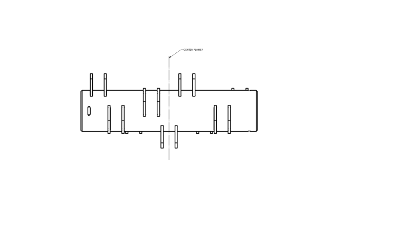
I am trying to design a balanced drum with equally weighted/spaced ears to spin at 1450RPM .
I just started learning about dynamic balancing so my grasp of it isn't completely solid.
I originally designed this machine so the drum had its static center of gravity at 0,0 thinking this would be a enough to produce a balance machine.
After building the machine and running it; it was clear this wasn't correct thinking. So i started doing research and discovered that statically balanced does not mean that it is dynamically balanced.
My first question is it possible to place these ear in a way that (theoretically) no extra balance weights are needed?
Is there something simple I'm overlooking? It seems like with equal radial distance and equal weights there should be a way to place these so it is dynamically balanced.
Because I'm human I was trying to keep the tabs in some kinda of sensible 60 deg arrangement or 72 deg arrangement. is this sabotaging the design?
Here is what I have now:
Goal:
To have a dynamically balanced drum with 9 equally spaced/weighted ears
technique:
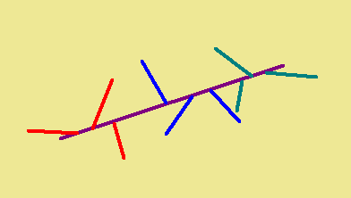
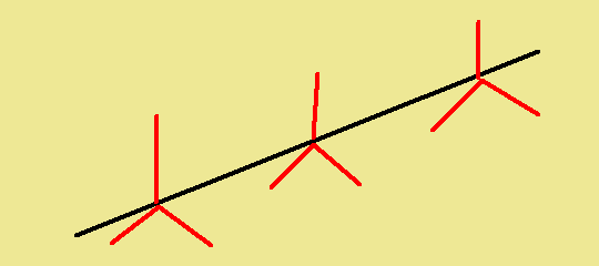
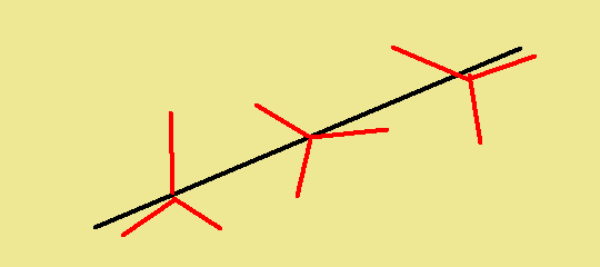
I am using the 2 plane balance method (graphical and analytical both seems to work for me)
Knowns:
All the added weights are the same, all the distance along the axis of rotation between weights are the same.
Unknowns
angular placement of ears (Im setting 0 degrees to be in line with ear 1) .
(I realize due to manufacturing tolerance some weight will be necessary, we have a VibXpert 2 (from Pruftechnik) hand held vibration analyzer to help final balance)
Or how do we get as close to 0 added weight as possible.
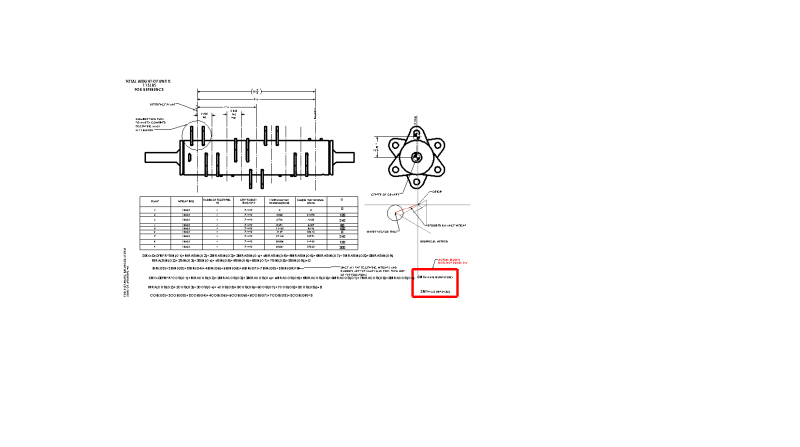
I am trying to solve the moments off the center of ears 1, I attached a PDF that shows my work and my thinking (again I am new to this) looking for guidance and to make sure I'm not chasing my tail on this one.
So far I have 8 unknowns and 2 equations.
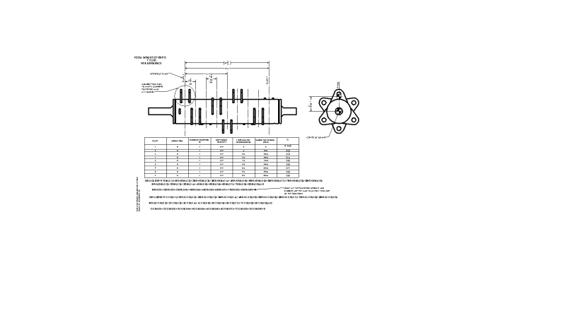
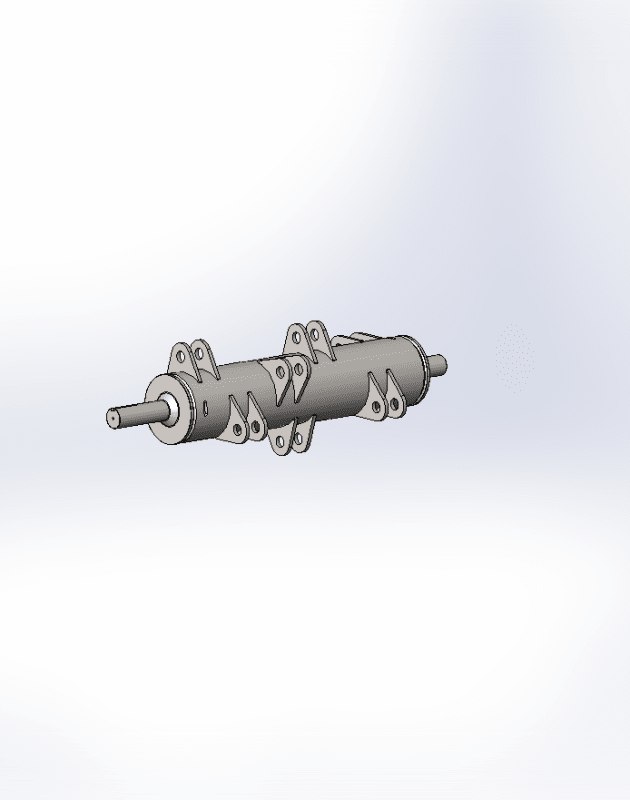
I have attached my work below along with a picture of the rotating piece in question.
Thanks for taking your time to read, any help would be greatly appreciated
I just started learning about dynamic balancing so my grasp of it isn't completely solid.
I originally designed this machine so the drum had its static center of gravity at 0,0 thinking this would be a enough to produce a balance machine.
After building the machine and running it; it was clear this wasn't correct thinking. So i started doing research and discovered that statically balanced does not mean that it is dynamically balanced.
My first question is it possible to place these ear in a way that (theoretically) no extra balance weights are needed?
Is there something simple I'm overlooking? It seems like with equal radial distance and equal weights there should be a way to place these so it is dynamically balanced.
Because I'm human I was trying to keep the tabs in some kinda of sensible 60 deg arrangement or 72 deg arrangement. is this sabotaging the design?
Here is what I have now:
Goal:
To have a dynamically balanced drum with 9 equally spaced/weighted ears
technique:
I am using the 2 plane balance method (graphical and analytical both seems to work for me)
Knowns:
All the added weights are the same, all the distance along the axis of rotation between weights are the same.
Unknowns
angular placement of ears (Im setting 0 degrees to be in line with ear 1) .
(I realize due to manufacturing tolerance some weight will be necessary, we have a VibXpert 2 (from Pruftechnik) hand held vibration analyzer to help final balance)
Or how do we get as close to 0 added weight as possible.
I am trying to solve the moments off the center of ears 1, I attached a PDF that shows my work and my thinking (again I am new to this) looking for guidance and to make sure I'm not chasing my tail on this one.
So far I have 8 unknowns and 2 equations.
I have attached my work below along with a picture of the rotating piece in question.
Thanks for taking your time to read, any help would be greatly appreciated